
Page 131 - 摩擦学学报2025年第10期
P. 131
1528 摩擦学学报(中英文) 第 45 卷
z/μm z/μm z/μm
(a) 2.52 (b) 1.94 (c) 3.38
−22.16 −4.75 −2.87
2.524 2.524
1.893 1.893 1.893 1.893 2.524 1.893 1.893
1.420 1.262 1.420 1.420 1.262
0.947
0.947 0.631 y/mm x/mm 1.262 y/mm 0.947 y/mm
0.473 0.473 0.631 x/mm 0.473 0.631
x/mm
(a1) 0 0 (b1) 0 0 (c1) 0 0
20.5 μm 4.6 μm 1.8 μm
200 μm 200 μm 200 μm
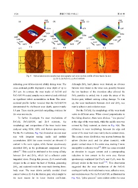
Fig. 8 Optical microscope morphology micrographs and cross-section profile of wear tracks (in air):
(a) Zr-4; (b) FeCrAl; (c) FeCrAl/CrN
indicating poor debris-removal ability during wear. The Although ZrO hard phases were formed, no obvious
2
cross-sectional profile displayed a wear depth of up to furrows were found in the wear scar, possibly because
20.5 µm. In contrast, the wear tracks of FeCrAl and the low hardness of the zirconium alloy allowed the
FeCrAl/CrN coated samples were minimal and exhibited ZrO particles to embed into it under the stress of the
2
no significant debris accumulation in them. The cross- friction pair, without causing cutting damage. To sum
sectional profile further revealed that the FeCrAl/CrN up, the wear mechanism between Zr-4 and ZrO was
2
demonstrated the shallowest wear depth, approximately mainly adhesion and oxidation wear.
1.8 µm. These results provided compelling evidence for For the FeCrAl, the morphology of the wear track
the wear rate results. varies in different areas. When viewed perpendicular to
To further investigate the wear mechanisms of the sliding direction, there were obvious “low grooves”
FeCrAl, FeCrAl/CrN, and Zr-4 substrate, the at the edge of the wear track, while the middle area was
morphology and composition of the wear tracks were covered by flaky material, as shown in Fig. 9(b). The
analyzed using SEM, EDS, and Raman spectroscopy. difference in wear morphology between the edge and
For the Zr-4 substrate, Fig. 9(a) showed an uneven wear center of the wear track was mainly due to contact stress.
scar with irregular tearing marks and nodular The contact stress distribution was uneven between the
accumulation. EDS line scans revealed an elevated O sphere (friction pair) and the plane (sample), with
content in the worn region, while Raman spectroscopy greater contact stress in the center area, making it more
[32]
identified ZrO as the predominant component of the susceptible to adhesive wear . EDS line scans revealed
2
[31]
debris . This could be attributed to the strong affinity an elevation in oxygen content and a corresponding
between Zr-4 and ZrO , which led to adhesion under reduction in iron content in the worn area. Raman
2
tangential stress. During this process, Zr-4 reacted with spectroscopy confirmed that Fe O and Cr O were the
2
3
3
2
oxygen in the air under the heat of friction, generating primary oxides in the wear track [33-34] . This observation
ZrO , and scattered inside the wear track forming three- suggested that the wear mechanism of the FeCrAl
2
body wear. The wear debris partially avoided direct coating primarily involved abrasive wear, adhesive wear,
contact between Zr-4 in the friction pair, which might be and oxidation wear. For the FeCrAl/CrN, as illustrated in
the main reason for its lower friction coefficient. Fig. 9(c), “plow grooves” were evident within the wear