
Page 128 - 摩擦学学报2025年第10期
P. 128
第 10 期 SU Yongyao, et al.: Exploring the Impact and Mechanism of CrN Interlayer on the Tribological ··· 1525
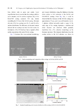
from defects such as pores and cracks. Local and element distribution along the thickness direction
magnification (inset) revealed that the coatings exhibit a (from surface to Zr-4 substrate) of the FeCrAl and
worm structure, and the surface roughness (R ) of the FeCrAl/CrN coatings. From Fig. 3(a), it could be
a
FerAl/CrN coating measured 56.6 nm, closely observed that the thickness of the FeCrAl coating was
resembling the 53.8 nm of the FeCrAl coating. The main approximately 9.9 µm, and it was well bonded to the Zr-
elements of the two coatings were Fe, Cr, and Al, with a 4 substrate without noticeable cracks or gaps. In the
uniform distribution. The difference in elemental content early stage of the coating deposition, a uniform and
between the two coatings was small. In other words, the dense structure was observed, which gradually
introduction of the CrN interlayer had a negligible effect transforms into a fine columnar morphology as the
on the composition of the outer FeCrAl coating. thickness increases. The elements distribution from the
Fig. 3 illustratesd the cross-sectional morphology coating surface to the Zr-4 substrate was shown in
1 μm 1 μm
Element Mass fraction/% Element Mass fraction/%
Fe 75.54 Fe 74.24
Cr 16.41 Cr 17.67
Al 8.05 Al 8.09
10 μm 10 μm
(a) R a =53.8 nm (b) R a =56.6 nm
Fig. 2 Surface morphology and composition of the coatings: (a) FeCrAl; (b) FeCrAl/CrN
(a) (a1)
FeCrAl
9.9 μm
Intensity/a.u. Cr
Zr
Fe
Al
4 μm 0 5 10 15 20
Scanning length/μm
(b) (b1)
N
FeCrAl Cr
8.1 μm Zr
Fe
Intensity/a.u.
CrN: 3.7 μm Al
0 5 10 15 20
4 μm
Scanning length/μm
Fig. 3 Sectional morphology and elements distribution of the coating: (a) FeCrAl; (b) FeCrAl/CrN