
Page 129 - 摩擦学学报2025年第10期
P. 129
1526 摩擦学学报(中英文) 第 45 卷
Fig. 3(a1). In the coating region, the elements Fe, Cr, CrN
FeCrAl
and Al were uniformly distributed without significant FeCrAl/CrN
Fe(110)
fluctuations or segregation. After the addition of the CrN Fe(211)
Intensity/a.u.
interlayer, the thickness of the FeCrAl and CrN coating Fe(200)
were approximately 8.1 µm and 3.7 µm, respectively. It
was also well bonded to the Zr-4 substrate. The cross-
section of the FeCrAl/CrN coating still exhibited a
columnar crystalline structure [Fig. 3(b)], but the
30 45 60 75 90
columns appear thicker compared to the FeCrAl coating. 2θ/(°)
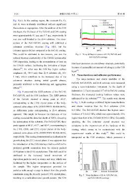
This could be attributed to two reasons, one was the Fig. 4 X-ray diffraction spectra of CrN, FeCrAl, and
reduced thermal conductivity of the CrN/Zr system after FeCrAl/CrN coatings
CrN deposition, leading to the accumulation of heat on
interlayer possesses an amorphous structure, potentially
the CrN/Zr surface, facilitating the formation of larger
because of an insufficient amount of nitrogen in the CrN
[23]
clusters , the other was the CrN has higher surface
[25]
layer .
roughness (R =58±3 nm) than Zr-4 substrate (R =15±
a
a
3.2 Nano-hardness and adhesion performance
1 nm), which contribute to the increased size of the
The nano-hardness and elastic modulus of the
columnar structure during initial growth phases,
FeCrAl, FeCrAl/CrN, and Zr-4 substrate were measured
primarily attributed to the shadowing and aggregation
[24]
effects . using a nano-indentation instrument. As the depth of
indentation (1.5 µm) exceeded 1/7 of the FeCrAl coating
Fig. 4 presented the XRD patterns of the FeCrAl,
thickness, the measured coating hardness values were
FeCrAl/CrN, and the CrN interlayer. The XRD pattern
of the FeCrAl showed a strong peak at 45.2°, influenced by the substrate [26-27] . The results were shown
corresponding to the (110) crystal plane of the body- in Fig. 5, both coatings exhibited higher nano-hardness
centered cubic phase of Fe (ICDD PDF2: 00-006-0696), and elastic modulus than the Zr-4 substrate (3.0±
no diffraction peaks corresponding to Zr-4 substrate 0.2 GPa). The FeCrAl/CrN showed the highest nano-
appeared. This might be because the thickness of the hardness of 5.0±0.2 GPa, which was approximately 25%
coating exceeded the detection depth of XRD, obscuring higher than that of the FeCrAl (4.0±0.1 GPa). Generally
the information of the substrate. For FeCrAl/CrN, three speaking, the fine columnar crystal structure was
peaks appear at 45.2°, 65.7°, and 82.9°, corresponding to conducive to the improvement of the hardness of the
the (110), (200), and (211) crystal planes of the body- coating, which seems to be contradictory with the
centered cubic phase of Fe (ICDD PDF2 00-006-0696), experimental results of this study . This could be
[28]
respectively. The coating demonstrated an inclination for interpreted as the CrN interlayer, which possesses a
growth along the (211) crystal plane. It was apparent that
15
the introduction of the CrN interlayer led to a shift in the
preferred growth orientation from the densely packed 12
Hardness/GPa
(110) plane to the (211) crystal plane. This shift could be 9
attributed to the increased lateral movement of
deposition particles such as atoms and ions, which was 6
facilitated by the higher temperature on the surface of
3
the sample. This higher temperature provided the
0
particles with enough energy to detach from the growth Zr CrN FeCrAl FeCrAl/CrN
constraints along the densely packed (110) crystal plane,
Fig. 5 Nano-hardness of Zr-4, CrN, FeCrAl,
resulting in a multi-directional growth pattern. The CrN and FeCrAl/CrN coatings