
Page 127 - 《摩擦学学报》2021年第5期
P. 127
716 摩 擦 学 学 报 第 41 卷
Fatigue side Fatigue side Fixed side Fixed side
100 μm 100 μm 100 μm 100 μm
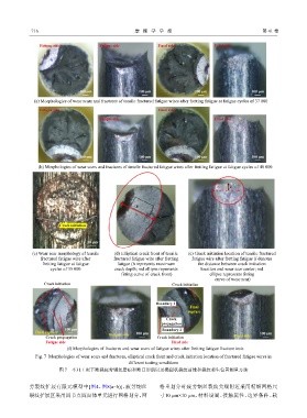
(a) Morphologies of wear scars and fractures of tensile fractured fatigue wires after fretting fatigue at fatigue cycles of 37 000
Fatigue side Fixed side
Fatigue side Fixed side
100 μm 100 μm 100 μm 100 μm
(b) Morphologies of wear scars and fractures of tensile fractured fatigue wires after fretting fatigue at fatigue cycles of 40 000
l
h
Crack initiation
50 μm
(c) Wear scar morphology of tensile (d) Elliptical crack front of tensile (e) Crack initiation location of tensile fractured
fractured fatigue wire after fractured fatigue wire after fretting fatigue wire after fretting fatigue (l denotes
fretting fatigue at fatigue fatigue (h represents maximum the distance between crack initiation
cycles of 35 000 crack depth; red ellipse represents location and wear scar center; red
fitting curve of crack front) ellipse represents fitting
curve of wear scar)
Crack initiation Crack initiation
Boundary 1
Final
rupture
Crack
propagation
100 μm Boundary 2
Final rupture 100 μm 100 μm
Fatigue side Fixed side
Crack propagation Crack initiation
Fatigue side Fixed side
(f) Morphologies of fractures and wear scars of fatigue wires after fretting fatigue fracture tests
Fig. 7 Morphologies of wear scars and fractures, elliptical crack front and crack initiation location of fractured fatigue wires in
different testing conditions
图 7 不同工况下断裂疲劳钢丝磨痕和断口形貌以及椭圆状裂纹前缘和裂纹萌生位置测量方法
劳裂纹扩展有限元模型中[图4、图8(a~b)],疲劳钢丝 格重划分时疲劳钢丝裂纹尖端附近采用精细网格尺
裂纹扩展区采用四节点四面体单元进行网格划分,网 寸10 μm×10 μm,材料设置、接触属性、边界条件、载