Page 123 - 《摩擦学学报》2021年第5期
P. 123

712                                     摩   擦   学   学   报                                 第 41 卷


                       (a)


                                                                   Tension     Servo electric
                               Tension    Loading wire            transducer     cylinder
                              transducer    fixtures
                                                    Fatigue
                                                     wire


                                             Fretting
                                             direction
                                                                Laser displacement
                                                                   transducer
                           Ball linear guide
                                           Guide pulley


                                                                Contact load
                                       Fatigue wire
                       (b)                                                  Loading wires
                        Fixed                                                             Fatigue load
                                                  Δx

                                                                                        F

                                                                Contact load

                       (c)                                   (d)
                                                                   F tmax
                                                                Tangential force/N       Cycles
                                                                0.8F tmax


                                                                 0.8F tmin
                                                                  F tmin

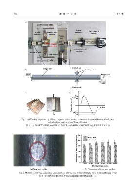
                    Fig. 1  (a) Fretting fatigue test rig; (b) working principal of test rig; (c) structure diagram of loading wire fixture;
                                            (d) calculation method of coefficient of friction
                        图 1    (a) 微动疲劳试验机; (b) 试验台工作原理; (c)加载钢丝夹具结构图; (d) 摩擦系数计算方法


                                                                     500      Major axis
                                                                    Dimensions of wear scar profiles/µm  300
                                                                              Minor axis
                                                                     400


                                                                     200

                                                                     100

                                                                       0
                                                                         5 000  10 000 20 000    30 000 40 000 50 000
                                                                                  Fretting fatigue cycles
                            (a) Wear scar profile                          (b) Dimensions of wear scar profiles

                  Fig. 2  Morphology of wear scar profile and dimensions of wear scar profiles of fatigue wires at distinct fatigue cycles
                                    图 2    钢丝磨痕轮廓形貌和不同疲劳周次疲劳钢丝磨痕轮廓尺寸
   118   119   120   121   122   123   124   125   126   127   128