Page 18 - 摩擦学学报2025年第4期
P. 18

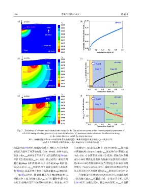
506                                    摩擦学学报(中英文)                                        第 45 卷


                (a)  h=0.06 t                                       (d)  0.20
                                                    ε p                                          t/R=0.04
                                                    0.000
                       Max: 0.023       Film        0.003               0.15
                                                    0.005
                                       Interface    0.008               Maximum substrate plastic strain, ε pmax  0.10
                                                    0.010
                                                    0.013               0.05
                                                    0.015
                                      Substrate     0.018

                     2 μm                           0.020               0.00 0.0  0.2  0.4  0.6  0.8   1.0
                                         t/R=0.04   0.023                         Indentation depth, h/t

                                                    ε p
                (b)  h=0.36 t                       0.000           (e)   8
                                        Film        0.009                        Stage I         t/R=0.04
                                                    0.018                 6
                                                    0.027
                                       Interface                                 Stage II    Stage III
                    Max: 0.080                      0.035
                                                    0.044                r (ε pmax )/t of radial direction  4
                                                    0.053
                                       Substrate    0.062                 2
                                                    0.071                                   Central axis
                     2 μm
                                         t/R=0.04   0.080                 0
                                                                           0.0   0.2  0.4   0.6  0.8   1.0
                                                                                   Indentation depth, h/t
                                                    ε p
                (c)  h=0.66 t                       0.000           (f)  0.0                     t/R=0.04
                                        Film        0.013                        Stage I
                                                    0.025               −0.5                  Stage III
                                                    0.038                        Stage II
                                      Interface     0.050                                 Film
                         Max: 0.113                                    z (ε pmax )/t of depth direction  −1.0
                                                    0.063
                                                    0.075                                        Interface
                                      Substrate     0.088               −1.5
                     2 μm                           0.101                                 Substrate
                                         t/R=0.04                       −2.0
                                                    0.113                  0.0   0.2  0.4   0.6  0.8   1.0
                                                                                   Indentation depth, h/t

                Fig. 3    Evolutions of substrate equivalent plastic strains for the film-substrate system with a contact geometric parameter of
                    t/R=0.04 during a loading process: (a~c) strain distributions, (d) maximum strain values and their locations along
                                           (e) the radial direction and (f) the depth direction
                         图 3    接触几何参数t/R=0.04的膜基系统加载过程中基体等效塑性变形演化:(a~c)变形分布,
                                     (d)最大变形数值及其沿基体(e)径向和(f)深度方向所处的位置

            为的影响如图6所示,随着t/R的减小,薄膜主应力分布及                        入深度h/t=1.0的加载过程中,t/R≥0.08时σ         1max 始终位
            演化行为发生了显著的变化. 当t/R=0.08时,拉伸主应力                     于薄膜底部;而t/R≤0.01时σ       1max 则始终位于薄膜表面.
            的最大值σ    1max 始终位于压头正下方的薄膜底部[图6(a)],               由此可知,对该膜基系统进行加载时,接触几何参数
            即在该加载范围(h       max /t=1.0)内,膜基系统主要处在薄             t/R≥0.08时薄膜初始裂纹为接触区底部的径向裂纹;
            膜承载(Stage I)和薄膜-基体共同承载(Stage II)阶段;                而t/R≤0.01时薄膜初始裂纹为接触区外沿表面的环
            而t/R=0.01时,σ  1max 则始终位于薄膜表面压头接触外                  形裂纹. 当0.02≤t/R≤0.067时,薄膜的初始裂纹位置及
            沿[图6(b)],膜基系统主要处在基体承载(Stage III)阶段.                形式则可结合其拉伸断裂强度σ             max 数值进行综合判定.
                如图6(c)所示,随着接触几何参数t/R数值增大,                          当接触几何参数0.02≤t/R≤0.067时,对薄膜拉伸
            薄膜拉伸主应力的最大值σ            1max 发生位置转移(图中箭            主应力最大值σ      1max 位置进行进一步的计算分析,结果
            头所示)的数值及压入深度h/t逐渐增大. 特别是,在压                        如图7所示. 加载过程中,随着t/R的改变,σ             1max 由薄膜
   13   14   15   16   17   18   19   20   21   22   23