Page 117 - 《摩擦学学报》2021年第4期
P. 117

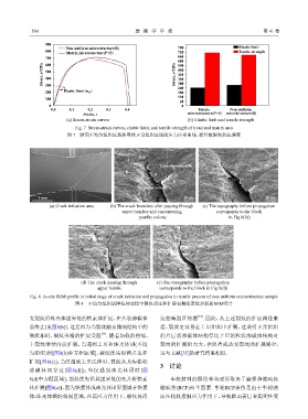
560                                     摩   擦   学   学   报                                 第 41 卷

                   900
                           Non-uniform microstructure(B)              780                    Elastic limit
                   800                                                                       Tensile strength
                           Matrix microstructure(P+F)                 720
                   700                                                660
                 Stress, σ/MPa  500                                  Stress, σ/MPa 600
                   600
                                                                      540
                                                                      480
                                                                      420
                   400
                                                                      360
                                                                      300
                   300
                                                                      240
                   200    Elastic limit (σ 0.2 )                      180
                                                                      120
                   100
                                                                      60
                    0                                                  0
                     0.0    0.1    0.2    0.3    0.4                          Matrix      Non-uniform
                                 Strain, ε                               microstructure(P+F)  microstructure(B)
                           (a) Stress-strain curves                       (b) Elastic limit and tensile strength

                              Fig. 7  Stress-strain curves, elastic limit, and tensile strength of tread and matrix area
                           图 7    踏面不均匀组织区域和基体正常组织区域的应力应变曲线、弹性极限和抗拉强度

                                                       P+F
                                                               Lamellar cementite
                                                  B
                                                             P                       P+F    B
                                                                    B
                                                       Granular cementite
                1 mm                                                    10 μm                           20 μm
                    (a) Crack initiation area  (b) The crack branches after passing through   (c) The topography before propagation
                                                upper bainites and encountering      corresponds to the block
                                                       pearlite colony                   in Fig.8(b))


                                      F   P
                                    P
                                B
                                         P  F                     P    F   P
                                               P
                                         B   B                 B
                                                                     P        F
                                                      20 μm                            20 μm
                                (d) The crack passing through   (e) The topography before propagation
                                       upper bainite           corresponds to the block in Fig.8(d))

             Fig. 8  In-situ SEM profile in initial stage of crack initiation and propagation in tensile process of non-uniform microstructure sample
                              图 8    不均匀组织试样拉伸过程中裂纹萌生和扩展初期的原位形貌的SEM照片

                                                                              [34]
            支裂纹沿珠光体团界处的铁素体扩展,在片状渗碳体                            这些薄弱区传播 . 因此,从上述裂纹的扩展路径来
            前终止[见图8(b)]. 这是因为当裂纹触及微观结构中的                       看,裂纹更容易在上贝组织中扩展,这说明正常组织
                                        [33]
            硬质相时,裂纹尖端的扩展受阻 . 随着加载的持续,                          的片层状渗碳体结构要比上贝的粒状渗碳体结构对
            主裂纹继续向前扩展,当遇到上贝和珠光体团(不均                            裂纹的扩展阻力大,会阻挡或改变裂纹的扩展路径,
            匀组织)时[图8(b)中方框区域],裂纹优先沿两者边界                        这与文献[35]的研究结果相似.

            扩展[图8(c)];当仅遇到上贝氏体时,裂纹从其短棒状
                                                               3    讨论
            渗碳体间穿过[图8(d)]);当仅遇到珠光体团时[图
            8(d)中方框区域],裂纹优先沿其团界处的先共析铁素                             车轮材料的服役寿命通常取决于磨损和滚动接
            体扩展[图8(e)],因为铁素体或珠光体团界面属于铁素                        触疲劳(RCF)两个因素. 车轮RCF损伤是由于车轮踏
            体-珠光体钢的薄弱区域,在高应力作用下,裂纹易沿                           面在轮轨接触应力作用下,导致踏面表层金属塑性变
   112   113   114   115   116   117   118   119   120   121   122