
Page 87 - 卫星导航2021年第1-2合期
P. 87
Shi et al. Satell Navig (2021) 2:5 Page 3 of 13
Table 1 GNSS parameters
Navigation satellite
Constellation Confguration
θ
Orbit type Altitude (km) Inclination (°) GNSS
GEO
BDS 27 MEO satellites in 3 21,477 55
planes MEO
10 IGSO satellites 35,709 55
7 GEO satellites 35,709 1.5
GPS 30 MEO satellites in 6 20,200 55
planes
GLONASS 24 MEO satellites in 3 19,084 65
planes
Galileo 24 MEO satellites in 3 23,044 55.5 θ 3 000 km
planes user
Space craft
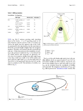
2010), e.g. the +Z antenna pointing nadir (pointing
down to the Earth), −Z or +X (pointing down to the
east). However, only the antenna in the +Z direction can
receive the signal from the opposite side of the Earth. Fig. 2 Visibility between satellite and spacecraft and beam width of
satellite signal at diferent altitudes
As mentioned in the introduction, for the most time in
SSTO the spacecraft height is higher than the navigation
satellites. Terefore, it is assumed that the spacecraft has
only one +Z direction antenna in the simulation. Accord- θ GNSS >θ earth
ing to the geometric analysis in Fig. 1, it is defned that θ GNSS <Φ (1)
θ user < 80 ◦
the GNSS satellite and spacecraft are physically vis-
ible when the navigation satellite bore-sight angle θ GNSS
is less than a half beam width of the GNSS satellite and Te θ earth is the earth shade angle mainly due to the sat-
spacecraft bore-sight angle θ user is less than half a Field of ellite altitude which are approximately 8.7 and 13.2° for
View (FOV) of the spacecraft, while the half FOV in this GEO/IGSO satellite and MEO satellite, respectively, and
study is considered as 80°. Te defnition of visibility is as the Φ is the satellite antenna main lobe angle. θ GNSS and
follows (Fig. 2). θ user can be calculated from the coordinates of satellite
and spacecraft. Te frequency distribution of θ GNSS and
θ user will be given in the “Simulation results” section. Te
SSTO
Apogee altitudeğ68 017 km
Inclinationğ16.3°
Inclinationğ16.3 to 0°
GEO
Altitudeğ35 788 km
Inclinationğ0°
Fig. 1 Shijian-20 launch process by CZ-5 Y3 via SSTO