
Page 102 - 《摩擦学学报》2021年第4期
P. 102
第 4 期 尹露, 等: 交错式扇贝阻尼密封动力特性研究 545
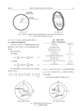
Even cavity
(C2aC4aC6aC8)
Even cavity
Odd cavity (C2aC4aC6aC8)
Y α (C1aC3aC5aC7aC9)
Y
Z X Z X
Odd cavity
(C1aC3aC5a
C7aC9)
(a) Axial view (b) Lateral view
Fig. 2 Schematic diagram of the cavity distribution for the interlaced scallop damper seal
图 2 交错式扇贝阻尼密封腔室分布示意图
22.5°、33.75°),表1列出了扇贝阻尼密封具体尺寸. 表 1 密封几何尺寸
1.2 密封动力特性求解方法 Table 1 Seal dimensions
Parameters Specifications
图3为转子分别沿X、Y方向做椭圆涡动模型, Ω为
Seal length,l/mm 35.7
涡动速度,ω为转子转速,a、b分别为椭圆轨迹的长、
Rotor diameter,d/mm 60
短半轴. Milling cutter diameter,d 1 /mm 26
涡动位移方程为 Seal radial clearance,C r /mm 0.2
10
Tooth number,N 1
X方向激励:
Cavity depth,h/mm 2.8, 3.3, 3.8, 4.3
Circumferential scallop cavity number,N 2 8
m ∑ m ∑
X=a· cos(Ω i t),Y=b· sin(Ω i t) (1) Tooth width,w 1 /mm 1.77
i=1 i=1 Cavity width,w 2 /mm 2
Y方向激励: Interlaced angle of the circumferential scallop cavity, 0, 11.25, 22.5,
α/(°) 33.75
Seal tooth shape Straight tooth
m ∑ m ∑
X=b· cos(Ω i t),Y=a· sin(Ω i t) (2)
i=1 i=1
转子表面所受密封气流力与涡动位移、涡动速度 式中:F 、F 为转子所受气流力;K 为密封刚度系数
Y
X
pq
[24]
的关系 表示为
(p、q=X、Y);X、Y为涡动位移;C 为密封阻尼系数; X ˙ 、
pq
[ ]
[ ] [ ] [ ] [ ] ˙
F X K XX K XY X C XX C XY X
− = · + · Y ˙ 为涡动速度.
F Y K YX K YY Y C YX C YY Y ˙
(3) 对公式(3)进行快速傅里叶变换(FFT),得:
Y Y
Whirling speed Ω
Whirling a
b speed Ω
O X O X
a
b
Rotor Rotor
Rotational speed ω
Stator Rotational speed ω
Stator
(a) X-direction excitation (b) Y-direction excitation
Fig. 3 Elliptical whirling orbits of the rotor
图 3 转子椭圆涡动模型