Page 34 - 《摩擦学学报》2021年第3期
P. 34

惠玉祥, 等: 考虑磨损的接触式端面密封模型及试验
            第 3 期              Exp-2-1  Exp-2-2  Exp-2-4 Exp-1-4  5.00  Experiemnt X-1                4.36 323
               Real-time temperature of end face, T/℃  200  Theoretical  Exp-2-3  Exp-1-1 Exp-1-4  Leakage quantity, Q/(mL/h)  4.00  3.23 3.15  2.45 3.65  2.09 4.06  3.95 3.34
               250
                                                                  4.50
                                                                        Experiemnt X-2
                     calculation
                                                                  3.50
               150
                                                                  3.00
                                                                  2.50
                                   Exp-1-2
               100
                                                                  2.00
                                                                  1.50
                50
                                                                  0.50
                                      Stable wear stage
                0
                                                                  0.00
                         360
                 0 Acceleration stage  720  900 1 080 1 260 1 440 1 620  1.00
                     180
                             540
                                                                           Experiemnt X-2
                                                                                           Experiemnt X-4
                              Experiment time, t/s                  Experiemnt X-1  Experiemnt X-3  Theoretical
                                                                                                     calculation
                Fig. 8    Comparison on experimental temperature and
                        theoretical model temperature            Fig. 10    Comparison on experimental leakage and theory
                    图 8    试验温度与理论模型温度对比图                                图 10    试验泄漏量与理论对比图
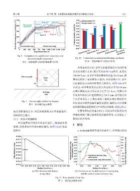
                                                                   由理论模型可知,静环实际磨损情况应为动环变
                                                               形形状和膜厚之和. 膜厚变化如图11(a)所示,其变化
                                                               为0.003 5 μm,而变形导致的磨损理论值为0.38 μm,膜
                   Thermocouple
                                      Static
                                       ring                    厚变化相对于变形磨损不足1%,因此忽略不计,静环
                              0.5                              实际磨损后应该和动环变形大致吻合. 从图11(b)中可
                                                               以看出,动环模拟变形最高点和最低点差为0.38 μm,
                                                               而静环磨损最高点和最低点之差为1.4 μm,但静环内
                                     Rotating
                                       ring
                                                               径处发生的较为严重的磨损差为0.71 μm,这可能是由
                                                               于内径处发生了石墨在高温下磨损后浸渍物的析出

                    Fig. 9    Thermocouple installation diagram
                                                               和结块而形成局部磨粒磨损造成的,磨损后可以观测
                          图 9    热电偶安装示意图
                                                               到内圆周靠近端面有较为严重的结块现象,如图12所示.
            油比理想情况要多,而采用数滴数来计算泄漏量时,                                但整体磨损趋势基本相同,因此该理论模型较为
            试验值将会偏小.                                           准确地预测了稳定磨损阶段的磨损情况,这也验证了

            2.3.3    密封环端面磨损                                   假设(5)的合理性.

                对试验磨损后的静环即软环进行三维端面形状
                                                               3    结论
            观测,得到其沿径向表面磨损情况,如图11(b)红色曲
            线所示.                                                   a. Archard磨损模型适用的条件下,沿窄端面径向


               0.768 0
                                                                0.50                                    1.0
               0.767 5                                          0.45                                    0.8
               0.767 0                                          0.40                                0.71  0.6
              Film thickness, h/μm  0.766 0  0.003 5         Simulated dynamic ring   deformation, u/μm  0.30  0.38  Simulated dynamic ring   0.69  0.2 Actual static ring deformation, u/μm
                                                                                                        0.4
                                                                0.35
               0.766 5
                                                                                                        0
                                                                0.25
               0.765 5
                                                                                                        −0.2
                                                                0.20
               0.765 0
                                                                                                        −0.4
               0.764 5
                                                                0.10
                                                                            Actual static ring deformation
                                                                                                        −0.8
               0.764 0                                          0.15        deformation                 −0.6
                                                                0.05
               0.763 5                                            0                                     −1.0
                   7.95 8.00 8.05 8.10 8.15 8.20 8.25 8.30 8.35 8.40 8.45 8.50  8.00  8.10  8.20  8.30  8.40  8.50
                                 Radius of seal face, r                         Radius of seal face, r
                            (a) Film thickness distribution      (b) Comparison on the deformation of ratating ring
                                   along radius                       and the wear of actual stationary ring

                                                Fig. 11  Wear analysis of seal face
                                                  图 11    端面密封磨损分析
   29   30   31   32   33   34   35   36   37   38   39