Page 116 - 《摩擦学学报》2020年第4期
P. 116

526                                     摩   擦   学   学   报                                 第 40 卷


                                                  100 μm                                            100 μm

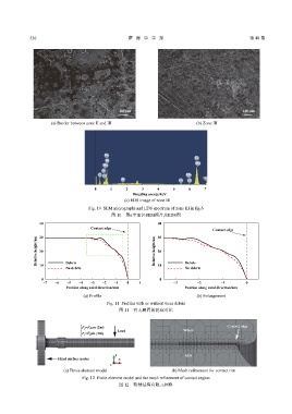
                      (a) Border between zone II and III                         (b) Zone III


                                            Fe
                                                                                Fe
                                            Ni
                                                                                 Mn
                                           Mn
                                           O
                                         C  Cr                               Mn
                                                   Si                     Cr  Cr    Fe
                                        0     1     2      3     4      5     6     7
                                                       Bingding energy/keV
                                                    (c) EDS image of zone III

                                     Fig. 10  SEM micrographs and EDS spectrum of zone III in fig.6
                                              图 10    图6中III区SEM照片及EDS图
                 40                                              40
                                      Contact edge
                                                                                        Contact edge
                                                                 30
                 30
                Relative height/um  20                          Relative height/um  20


                            Debris
                 10
                            No debris                            10          Debris
                                                                             No debris
                  0                                               0
                   −7  −6   −5   −4   −3   −2   −1   0    1             −3       −2        −1        0
                            Position along axial direction/mm               Position along axial direction/mm
                                   (a) Profile                                   (b) Enlargement

                                             Fig. 11  Profiles with or without wear debris
                                                  图 11    有无磨屑的轮廓对比


                                                                                              Contact edge
                                  F y =F 0 cos (2πt)
                                                 Load                       Wheel
                                  F z =F 0 sin (2πt)


                                                y                           Axle
                         Fixed surface nodes     x
                                              z
                           (a) Finite element model                    (b) Mesh refinement for contact rim

                                   Fig. 12  Finite element model and the mesh refinement of contact region
                                                  图 12    轮轴结构有限元网格
   111   112   113   114   115   116   117   118   119   120   121