
Page 82 - 《振动工程学报》2026年第5期
P. 82
轴承故障
轴承故障
−2
·
幅值
故障程度
第 阶模态周围
−2
·
幅值
故障程度 振幅之和
第 阶模态周围 振幅之和
1286 振 动 工 程 学 报 第 39 卷
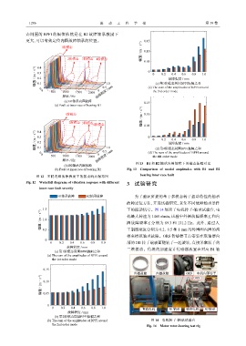
态周围的 BPFI 的幅值依然是在 B2 故障轴承激励下
更大,可以有效定位内圈故障轴承的位置。 0.15
幅值 / (m·s −2 ) 0.10
1阶模态
2阶模态 3阶模态 4阶模态 0.05
幅值 / (m·s −2 ) 0.4 0 0 0.2 故障程度 / mm 0.8 1.0
0.3
0.4
0.6
0.2
(c) 第3阶模态周围BPFI振幅之和
0.1
0 0.5 1.0 (c) The sum of the amplitudes of BPFI around
0 0
500 1000 1500 2000 故障程度 / mm the 3rd order mode
频率 / Hz
(a) B1轴承内圈故障
0.15
(a) Fault at inner race of bearing B1
幅值 / (m·s −2 )
1阶模态 0.10
2阶模态 3阶模态
4阶模态 0.05
幅值 / (m·s −2 ) 0.3 0 0 0.2 故障程度 / mm 0.8 1.0
0.4
0.4
0.6
0.2
0.1
(d) 第4阶模态周围BPFI振幅之和
0 0.5 1.0 (d) The sum of the amplitudes of BPFI around
0 0
500 1000 1500 2000 故障程度 / mm the 4th order mode
频率 / Hz
(b) B2轴承内圈故障 图 13 B1 和 B2 轴承内圈故障下的模态振幅对比
(b) Fault at inner race of bearing B2 Fig. 13 Comparison of modal amplitudes with B1 and B2
图 12 不同内圈故障程度下的振动响应瀑布图 bearing inner race fault
3 试 验 研 究
Fig. 12 Waterfall diagrams of vibration response with different
inner race fault severity
B1轴承故障 B2轴承故障 为了验证所提的基于多模态转子振动特性的轴承
故障定位方法,开展试验研究,采集不同故障轴承条件
1.5 下的振动信号。图 14 展示了电机转子-轴承试验台,电
幅值 / (m·s −2 ) 1.0 机最大转速为 f i 分别为 89.3 和 131.2 Hz。此外,通过人
1460 r/min,试验中外圈故障频率
f o 和内
圈故障频率
的外圈和内圈的沟
和
工制造宽度分别为
1 mm
0.2、0.5
0.5
槽来模拟轴承故障。ORS 传感器节点安装在联轴器内
0
0 0.2 0.4 0.6 0.8 1.0 部的 DE 转子端表面随转子一起旋转,直接采集转子的
故障程度 / mm 三维振动。传统的加速度计传感器放置在对应 轴
(a) 第1阶模态周围BPFI振幅之和 B1
(a) The sum of the amplitudes of BPFI around
the 1st order mode
0.15
外圈故障 内圈故障 ORS OHS
电机内部转子
幅值 / (m·s −2 ) 0.10
0.05
0
0 0.2 0.4 0.6 0.8 1.0
直流电机 B1 轴承 感应电机 B2 轴承
故障程度 / mm
(b) 第2阶模态周围BPFI振幅之和
(b) The sum of the amplitudes of BPFI around 图 14 电机转子-轴承试验台
the 2nd order mode
Fig. 14 Motor rotor-bearing test rig
−2
·
幅值
故障程度
第 阶模态周围 振幅之和
−2
·
幅值
故障程度
第 阶模态周围 振幅之和