
Page 193 - 卫星导航2021年第1-2合期
P. 193
Li et al. Satell Navig (2021) 2:1 Page 7 of 14
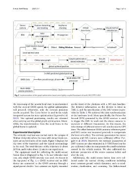
Fig. 2 Implementation of the graph-optimization based semi-tightly coupled framework of multi-GNSS PPP/S-VINS
the timestamp of the newest local state is synchronized on the front of the platform with a 505 mm baseline.
with the current GNSS epoch, the global optimization Te detailed information on the devices is listed in
will proceed. Otherwise, only the forecast positions Table 2, and the specifcation of the IMU sensor is pro-
can be acquired. Te Ceres Solver is used in the triple vided in Table 3. We achieved the time synchronization
integrated system for state optimization (Agarwal et al. at the hardware level. More specifcally, the Pulses Per
2012). Te optimal positioning results are obtained Second (PPS) generated by the GNSS receiver is used
after carrying out the global graph optimization. Mean- to trigger the IMU to work and the stereo cameras to
while, the transformation from the local frame to the exposure at diferent frequencies. By this means, the
global frame is updated. time stamps of diferent sensors will synchronize to GPS
time. Te ofset between GNSS antenna reference point
Experimental description and IMU center was measured precisely to compensate
Te vehicular road test was carried out in the campus of the lever-arm efect. Te extrinsic parameters for stereo
Wuhan University where the trees with dense forest can- cameras and IMU-camera were calibrated ofine (Fur-
opies are on both sides of the roads. Figure 3 displays the gale et al. 2013). Moreover, the extrinsic parameters of
top view of the trajectory and the typical surroundings IMU-camera are also estimated in S-VINS based on the
in the road. Te total distance of the trajectory is about pre-calibrated values to compensate the small variations
2670 m, and it takes about 12 min in our experiment. caused by the vehicle motion. We also calibrated the
Te equipment used for collecting the multi-sensor intrinsic parameters of the stereo cameras before and
fusion data is displayed in Fig. 4. In our vehicular road after the test.
test, only single GNSS antenna was used. As shown in Additionally, the multi-sensor fusion data were col-
the top panel of Fig. 4, a GNSS receiver and an IMU lected under the normal driving conditions including
device are connected to the GNSS antenna through a most common ground vehicle dynamics, such as accel-
signal power divider. Two cameras are tightly mounted eration, deceleration, and cornering. Te bidirectional