
Page 190 - 卫星导航2021年第1-2合期
P. 190
Li et al. Satell Navig (2021) 2:1 Page 4 of 14
(previous frame to current frame) and backward (cur- After the initialization of estimator, a tightly coupled
rent frame to previous frame) feature tracking are both sliding window-based VIO is carried out to achieve
implemented to acquire high quality tracking results. accurate and robust state estimation, serving as local
Meanwhile, new corner features are detected to main- constraints in the global fusion. Te defnition of state
tain a certain number of features (e.g., 100–300) in each vector in the sliding window can be written as (Qin
image (Shi and Tomasi 1994). Te stereo matches are et al. 2018):
also obtained by the KLT sparse optical fow algorithm
b
between left and right images. As for the raw Inertial χ l vio =[x 0 , x 1 , . . . x n , x , 0 , 1 , . . . m ] (9)
c
Measurement Unit (IMU) measurements, the IMU pre-
integration technique is used to generate relative IMU l vio l vio l vio (10)
measurements between two consecutive states in VIO x k =[p b k , v b k , q b k , b a , b g ], k ∈[0, n]
sliding window (Lupton and Sukkarieh 2012). For the
IMU state propagation in pre-integration, the mid-point x =[p , q ] (11)
b
b
b
c
c
c
integration is used for the discrete-time implementation.
To propagate the uncertainty of the state, the covariance where χ l vio denotes the complete state vector including
b
of the IMU state can be computed recursively, referring the IMU state vector x k , the extrinsic parameter x of
c
to Qin et al. (2018). IMU-camera, and the inverse depth l of the l th feature
An initialization procedure is required for the stereo from its frst observation; c and b represent the camera
VIO. For each frame in the sliding window, we trian- frame and IMU frame, respectively. n and m are the quan-
gulate all features observed in the stereo pairs. Based tities of keyframes and features in the sliding window,
on these triangulated features, a Perspective-n-Point respectively; the x k consists of the IMU states at the time
l vio
(PnP) method is used to estimate the poses of all other when the k th image is captured; the position p , veloc-
b k
l vio
frames in the window (Lepetit et al. 2009). Additionally, ity v , and orientation q of the IMU center is with
l vio
b k
b k
the pre-integration factor is constructed between each respect to the local reference frame l vio which is defned
frame in the window. When the window size reaches by the frst IMU pose; b a and b g represent the accelerom-
10, a visual-inertial bundle adjustment is performed to eter bias and gyroscope bias, respectively.
obtain the optimized states in the window. A maximum posteriori estimation of the VIO system
states can be acquired by minimizing the sum of a priori
and the Mahalanobis norm of all measurement residuals:
2 � 2 �
� � � � �
� � 2 � b k � � � c j � (12)
min � r p − H p χ � + �r I (ˆ z , χ)� b + ρ �r C (ˆ z , χ)� c j
b k+1 k l
χ l vio P b P l
k∈I k+1 (l,j)∈C
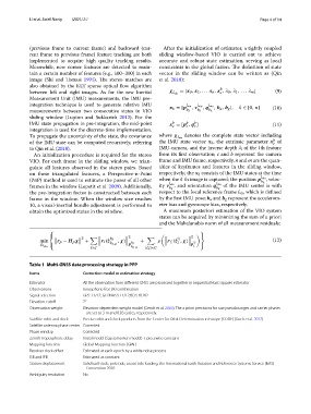
Table 1 Multi-GNSS data processing strategy in PPP
Items Correction model or estimation strategy
Estimator All the observation from diferent GNSS are processed together in sequential least squares estimator
Observations Ionospheric-free (IF) combination
Signal selection GPS: L1/L2; GLONASS: L1/L2;BDS: B1/B2
Elevation cutof 7°
Observation weight Elevation-dependent weight model (Gendt et al. 2003). The a priori precisions for raw pseudoranges and carrier phases
are set to 3 m and 0.03 cycles, respectively.
Satellite orbit and clock Precise orbit and clock products from the Center for Orbit Determination in Europe (CODE) (Dach et al. 2017)
Satellite antenna phase center Corrected
Phase windup Corrected
Zenith Tropospheric delay Initial model (Saastamoinen model) + piecewise constant
Mapping function Global Mapping Function (GMF)
Receiver clock ofset Estimated at each epoch by a white noise process
ISB and IFB Estimated as constant
Station displacement Solid Earth tide, pole tide, ocean tide loading, the International Earth Rotation and Reference Systems Service (IERS)
Convention 2010
Ambiguity resolution No