
Page 139 - 卫星导航2021年第1-2合期
P. 139
Liu et al. Satell Navig (2021) 2:6 Page 6 of 17
precisely known receiver coordinates. Te datasets
Trimble Zephyr Geodetic 2 Trimble Zephyr Geodetic 2 were collected in the static experiments at the Wuhan
Antenna #1 Antenna #2
University campus. Te data for the zero and short
about 3.9 m baselines were collected under an elevation cut-of
angle of 10° on June 9, 2020. Figure 4 shows the esti-
Spliter mated phase and code DISBs between two Trimble
Alloy receivers for BDS-3/BDS-2 B1I/B3I signals.
Figure 5 shows the estimated phase and code DISBs
Trimble Alloy Trimble Alloy iGMAS iGMAS
#1 #2 #1 #2 between the Trimble Alloy and Javad TRE_3 receivers.
Fig. 2 Confguration of multi-GNSS receivers and antennas at SGG Table 4 gives the estimated phase and code DISBs [the
stations average (AVE) values together with the standard devia-
tions (STDs)] for both the same and diferent receiver
types. As shown in Figs. 4, 5, and Table 4, regardless
of the same or diferent receiver types used at both
version 3.7.9) and JAVRINGANT_G5T NONE endpoints of a baseline, the estimated phase and code
antenna) were also used. Te station WUH2 was also DISBs were all approximately zero and thus negligible.
located in Wuhan University and separated by approxi- For example, the phase and code DISBs for two Trim-
mately 371 m from the SGG building. Te locations ble Alloy receivers were 0/0 cycles and − 0.08/0.01 m
of the stations and the observational conditions of the for B1I/B3I signals, respectively, and for the Trim-
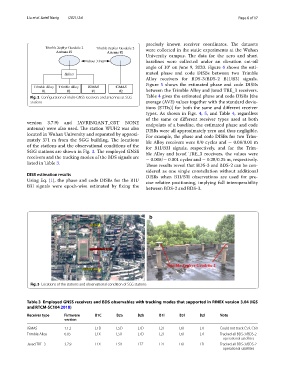
SGG stations are shown in Fig. 3. Te employed GNSS ble Alloy and Javad TRE_3 receivers, the values were
receivers and the tracking modes of the BDS signals are − 0.008/− 0.001 cycles and − 0.28/0.25 m, respectively.
listed in Table 3.
Tese results reveal that BDS-3 and BDS-2 can be con-
sidered as one single constellation without additional
DISB estimation results DISBs when B1I/B3I observations are used for pre-
Using Eq. (1), the phase and code DISBs for the B1I/ cise relative positioning, implying full interoperability
B3I signals were epoch-wise estimated by fxing the
between BDS-2 and BDS-3.
Fig. 3 Locations of the stations and observational condition of SGG stations
Table 3 Employed GNSS receivers and BDS observables with tracking modes that supported in RINEX version 3.04 (IGS
and RTCM-SC104 2018)
Receiver type Firmware B1C B2a B2b B1I B3I B2I Note
version
iGMAS 1.1.2 L1D L5D L7D L2I L6I L7I Could not track C59, C60
Trimble Alloy 6.05 L1X L5X L7D L2I L6I L7I Tracked all BDS-3/BDS-2
operational satellites
Javad TRE_3 3.7.9 L1X L5X L7Z L2I L6I L7I Tracked all BDS-3/BDS-2
operational satellites