Page 38 - 摩擦学学报2025年第10期
P. 38

第 10 期                 高冰鉴, 等: 悬臂梁支撑摩擦副沿轴向双向滑动摩擦行为规律研究                                      1435


                       (a)      0.19      Forward
                                          Reverse                                     −0.03
                                0.13
                             Friction force/N  0.07                                   −0.11 Friction force/N

                                                                                      −0.19
                                0.01
                                                                                      −0.27
                               −0.05
                                                                                      −0.35
                                   0               5 000           10 000
                                                           Time/s
               (b)                                 Z/μm        (c)                                  Z/μm
                  S a : 0.206 μm                   1.5             S a : 0.186 μm                   1.0
                                                   1.2                                              0.8
                                                   0.9                                              0.6
                                                   0.6                                              0.4
                                                   0.3                                              0.2
                                                   0.0                                               0
                   0                              −0.3             0                               −0.2
                   200                        800  −0.6            200                         800  −0.4
                                                  −0.9
                                                                                                   −0.6
                     400                   600    −1.2                400                  600     −0.8
                                        400       −1.5               Y/μm               400        −1.0
                        600              X/μm     −1.8                  600               X/μm     −1.2
                    Y/μm
                                    200           −2.1                              200            −1.4
                           800                    −2.4                     800                     −1.6
                                0                                               0
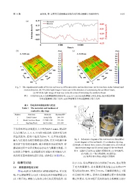
              Fig. 3    The experimental results of friction and wear in different relative motion directions: (a) friction force in the forward and
                      reverse direction; (b) 3D white light image of wear scar in the direction of compressing the cantilever beam;
                             (c) 3D white light image of wear scar in the direction of stretching the cantilever beam
                      图 3    不同相对运动方向的摩擦磨损试验结果:(a)正向与反向运动的摩擦力变化曲线;(b)压缩悬臂梁
                                   方向试验磨痕三维白光图;(c)拉伸悬臂梁方向试验磨痕三维白光图


                      表 1    导电滑环环刷副材料与性能                       (a)                    (b)
                    Table 1    The materials and hardness of                5
                           conductive slip rings
                                                                                 3
              Number     Structures    Materials  Hardness/HV                 2
                1       Brush Contact  AuAgCuZn   280~330
                2    Brush Cantilever Beam  C1720R-1/2H  372~434
                3      Slip Ring Track  Au-Co Alloy  210~240        1

            下保持相对运动线速度大小均为229.3 mm/s,测试时
            长为分别为1、2、4、8、15 h的10组试验. 试验环境为封                                   4
            闭金属腔体,腔体中温度为25±1 ℃. 在开始试验前,
            触头与汇流盘均使用酒精进行清洗,用无尘纸擦干净                              Fig. 4    Schematic diagram of the test bench (a) Simplified
                                                                 model diagram of the test bench: (1) conductive slip ring;
            表面留下的有机污染物,减少摩擦界面杂质残留. 摩                           (2) brush; (3) triaxial force sensor; (4) rotary table; (5) vertical
            擦试验过程中全程采集动态法向力与摩擦力数据,并                              displacement stage and (b) actual image of the test bench
            记录其力学特性,在试验前后对试验中所用触头与汇                             图 4    试验台示意图 (a) 试验台模型简图:(1) 导电滑环;
                                                                       (2) 电刷;(3) 三轴力传感器;(4) 旋转台;
            流盘的表面形貌情况进行表征. 试验设计如图5所示.                                   (5) 竖直位移台和(b) 试验台实物图

             2    结果与讨论                                        比于正向,反向摩擦时法向力增加了56.6%. 进而导致

             2.1    摩擦磨损性能分析                                   了更大的摩擦力,此时摩擦系数均值由正向的0.377
                图6(a~b)所示为典型的8 h摩擦试验结果,可以发                     变为反向的0.451,增大了19.6%,且摩擦系数的上下限
            现,在压缩悬臂梁方向(以下称反向)和拉伸悬臂梁方向                          在反向时明显增大,表明在反向摩擦过程中系统接触
            (以下称正向),摩擦力与法向力均有相反变化趋势. 相                         稳定性更差. 综合10组正反向的法向力和摩擦力进行
   33   34   35   36   37   38   39   40   41   42   43