
Page 26 - 《摩擦学学报》2021年第4期
P. 26
第 4 期 刘明, 等: 恒定大载荷划痕试验下紫铜的三维形貌及划痕硬度分析 469
60
100
50 200
80
40
150
60
30
100
40
20
50
20
10
0 0
μm −20 μm μm
0
−10 −50
−40 −100
−20
−60
−30 −150
−80
−40 −200
200 μm 200 μm −100 200 μm
−50 −250
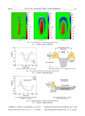
(a) 12 N (b) 60 N (c) 108 N
Fig. 1 3D morphologies of scratches under different loads
图 1 不同载荷下划痕的三维形貌图
100 Scratch width for scratch
hardness(D H )
50 width(D w )
Scratch
Height/μm 0 Side pile-up A 1 A 2
height(H S )
−50
12 N Side pile-up
−100 60 N width(D S )
108 N Scratch depth(H D ) A 3
−150
−200 0 200 400 600 800 1 000
Distance/μm
(a) Cross-sectional profile of scratches (b) Schematic illustration of a scratch (cross-section)
Fig. 2 Cross-sectional profile of scratches under different loads
图 2 不同载荷下划痕的横向剖面图
200
12 N
150 60 N
Scratch direction 108 N Scratch direction
100
Height/μm 50 Front pile-up
0 height(H F ) Scratch length(d)
−50 Scratch volume(V)
−100 Front pile-up
thickness(D T )
−150
−1 000 −500 0 500 1 000 1 500
Distance/μm
(a) Longitudinal section profile along the (b) Schematic illustration of scratch
centerline of scratches (Longitudinal-section)
Fig. 3 Longitudinal profile of scratches under different loads
图 3 不同载荷下划痕的纵向剖面图
半椭圆形的半长轴D 和半短轴D 随着正压力的变化 使前端材料堆积能及时转移至划痕两侧,此时半长轴
y x
曲线,结果如图5所示. 较小的正压力下,压头的移动 D 和半短轴D 的增长速率较为平缓,在正压力F 超过
n
x
y