
Page 53 - 《摩擦学学报》2021年第1期
P. 53
50 摩 擦 学 学 报 第 41 卷
Input load, speed, material parameters, geometric parameters
and rough surface data
Input initial value of pressure and Decompose the rough surface
central film thickness into a group of sinusoidal
surfaces
Calculation of elastic deformation and
Correction of central filmthickness Correction of pressure Calculated the pressure according to Calculate the elastic deformation
film thickness distribution
for each sinusoidal surface
film thickness distribution
No Pressure
convergence Calculate the corresponding
pressure fluctuation
Yes according to the strain
Calculation of load
Use IFFT to calculate the
No
Load balancing verall film thickness and
pressure fluctuation
Yes
Superposition
results
Fig. 2 Flow chat of EHL point contact simulation
图 2 点接触弹流润滑计算分析流程
表 1 几何与材料参数
Table 1 Geometric and material parameters
0.4
Parameters Specification 0.3
R 20 mm 0.2
11
E′ 2.21×10 Pa Z/m 0.1
0
0.05 Pa·s
η 0
−0.1
−8
α 2.00×10 Pa −0.2
0.3
v 1,2
600
500
400 400
300
Y 200 200
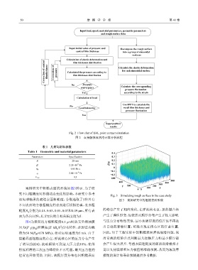
案例研究中粗糙表面的形貌如图3所示. 为了研 0 0 100 X
究不同粗糙度对形貌动态变化的影响,本研究中参考
Fig. 3 Simulating rough surface in the case study
深沟球轴承的滚道表面粗糙度,分别选取了5种具有 图 3 案例研究中的粗糙表面形貌
不同表面均方根粗糙度的表面进行模拟仿真,表面粗
糙度R 分别为0.01、0.03、0.05、0.07和0.09 μm,所有表 的峰谷产生了相应变化. 在弹流核心区,虽然微凸体
q
面为各向同性,X、Y方向的自相关长度均为5. 产生了弹性形变,但依然对膜厚分布产生了较大影响.
图4为表面均方根粗糙度0.1 μm时的无量纲油膜 与压力分布特性类似,最小油膜厚度的位置也不再是
压力(P=p/p )和厚度(H=hR /b )分布特性,此时法向载 出口处的紧缩位置,可能出现在核心区的任意位置.
2
x
H
荷为50 N(P =670 MPa)、相对运动速度为5 m/s. 由于 因此,对于工程实际中的粗糙表面弹流润滑问题,采
H
接触界面粗糙度的存在,弹流核心区的压力分布产生 用常规的经验公式判断最大接触压力和最小膜厚都
了明显的波动,波动幅值可到最大压力的10%,使得 会产生很大误差. 考虑表面粗糙度的弹流润滑模型才
弹流润滑的二次压力峰特征不再明显,最大压力值的 足以支持膜厚和压力极值的准确预测,从而为滚动摩
位置也开始变动. 同时,油膜厚度分布也因粗糙表面 擦副的设计和寿命预测提供参考数据.