
Page 30 - 《摩擦学学报》2020年第6期
P. 30
第 6 期 郭曼利, 等: 不同压力角下自由端面对渐开线直齿轮弹流润滑性能的影响 713
1.2 1.2 1.2
ES-ES ES-ES ES-ES
1.0 FS-ES 1.0 FS-ES 1.0 FS-ES
FS-FS FS-FS FS-FS
0.8 0.8 0.8
P/GPa 0.6 P/GPa 0.6 P/GPa 0.6
0.4 0.4 0.4
0.2 0.2 0.2
0.0 0.0 0.0
0 4 8 12 16 20 24 0 4 8 12 16 20 24 0 4 8 12 16 20 24
y/mm y/mm y/mm
(a1) α=15° (a2) α=20° (a3) α=25°
2.5 2.5 2.5
ES-ES ES-ES
FS-ES FS-ES
2.0 FS-FS 2.0 FS-FS 2.0
h/µm 1.5 h/µm 1.5 h/µm 1.5
1.0 1.0 1.0
ES-ES
FS-ES
0.5 0.5 0.5 FS-FS
0.0 0.0 0.0
0 4 8 12 16 20 24 0 4 8 12 16 20 24 0 4 8 12 16 20 24
y/mm y/mm y/mm
(b1) α=15° (b2) α=20° (b3) α=25°
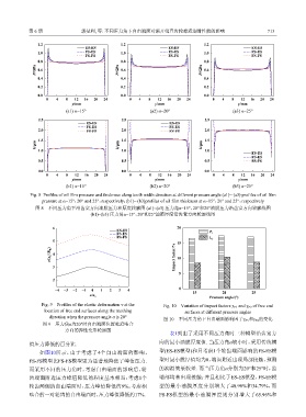
Fig. 8 Profiles of oil film pressure and thickness along tooth width direction at different pressure angle (a1)~ (a3) profiles of oil film
pressure at α=15°,20° and 25°,respectively;(b1)~ (b3)profiles of oil film thickness at α=15°,20° and 25°,respectively
图 8 不同压力角下沿齿宽方向油膜压力和厚度轮廓图 (a1)~(a3) 压力角α=15°,20°和25°油膜压力沿齿宽方向轮廓线图
(b1)~(b3) 压力角α=15°,20°和25°油膜厚度沿齿宽方向轮廓线图
6 20
ES-ES
FS-ES P 1
FS-FS l P2
5 15
v/(a h 2 /R K ) 4 Impact factor/% 10
3
5
2
−4 −3 −2 −1 0 1 2 3 4 0
15 20 25
x/a h
Pressure angle/(°)
Fig. 9 Profiles of the elastic deformation v at the Fig. 10 Variation of impact factors γ P1 and γ P2 of free end
location of free end surfaces along the meshing surfaces at different pressure angles
direction when the pressure angle α is 20° 图 10 不同压力角下自由端面影响因子γ P1 和γ P2 的变化
图 9 压力角α为20°时自由端面位置处沿啮合
方向的弹性变形轮廓图
表1列出了采用不同压力角时三种模型沿齿宽方
向的最小油膜厚度值. 当压力角α较小时,采用传统模
值压力降低的百分比.
如图10所示,由于考虑了4个自由端面的影响, 型(ES-ES模型)和只考虑1个轮齿端面影响的FS-ES模
型时最小膜厚值均为0,端面附近出现局部接触,预测
FS-FS模型比FS-ES模型更为显著地降低了峰值压力.
而采用不同的压力角时,考虑自由端面的影响后,轮 的润滑效果较差. 而当压力角α分别为20°和25°时,齿
齿端面附近压力峰值降低的程度基本相当:考虑1个 端部均未出现接触;并且相比于ES-ES模型,FS-ES模
轮齿两侧的自由端面时,压力峰值降低约9%;考虑相 型的最小油膜厚度分别增大了40.96%和34.79%,而
啮合的一对轮齿的自由端面时,压力峰值降低约17%. FS-FS模型的最小油膜厚度则分别增大了65.96%和