


Page 118 - 《爆炸与冲击》2026年第9期
P. 118
第 46 卷    任    杰,等: 不同直径钨纤维增强金属玻璃复合材料长杆弹自锐行为及侵彻/穿甲性能                            第 9 期

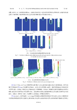
               现象,如图中      AA'、BB'虚线区域所示。因塑性变形而发生弯折的钨纤维堆积在弹体头部,在随后的侵彻
               过程中才被剪断,因此弹体破坏模式主要表现为塑性流动+剪切破坏的模式。


                            15 μs       60 μs      130 μs         10 μs       40 μs       90 μs
                               (a) d=0.3 mm, WF rod, v=800 m/s      (b) d=0.7 mm, WF rod, v=1 600 m/s
                                                                          Effective plastic strain
                                                                               3.199
                                                                               2.879
                                                                               2.559
                                                                               2.240
                                                                               1.920
                                                                               1.600
                                                                               1.280
                                                                               0.960
                                                                               0.640
                                                                               0.320
                                        5 μs        30 μs       70 μs          0
                                          (c) d=1.0 mm, WF rod, v=2 000 m/s
                                          图 15    复合材料弹体侵彻靶板弹靶应变演化历程
                        Fig. 15    Evolutions of effective strain within the projectile and target materials in the penetration process
                                                 of composite rods into steel targets


                                                                                       Effective plastic strain
                                                                                             3.0
                                                                                             2.7
                                                                                             2.4
                                                                                             2.1
                                                                                             1.8
                                      A′                                                     1.5
                                                                                             1.2
                                                                                             0.9
                  A               B′                                                         0.6
                   B                                                                         0.3
                                                                                             0
                 (a) d=0.3 mm, v 0 =800 m/s, t=60 μs  (b) d=0.7 mm, v 0 =1 600 m/s, t=40 μs  (c) d=1.0 mm, v 0 =2 000 m/s, t=30 μs
                                             图 16    复合材料弹体弹头区域的应变分布
                                    Fig. 16    Distribution of effective strain in the noses of composite rods

                   图  16(b) 中显示,d=0.7 mm  纤维弹体头部纤维并未发生剧烈弯折现象,而是出现轻微弯曲,且弹头边
               缘层厚度相对于图         16(a) 中的情形有所减小。这是由于在更高撞击速度下,钨纤维受到临近基体的剪切
               冲击作用进一步增强,纤维在发生轻微弯曲后立即被剪断。同时由于外侧钨纤维受到基体的约束作用
               较弱,容易发生屈曲回流(参见圆圈区域)。因此弹体在侵彻过程的破坏模式主要表现为屈曲回流+剪切
               破坏。该模式一定程度上减小了侵彻阻力,进而提高了弹体的侵彻效率。
                   图  16(c) 显示,在更高速度下,d=1.0 mm        纤维弹体头部钨纤维并未发生弯折变形,而是在基体强剪切
               冲击作用和靶板挤压作用直接发生剪切断裂,因此弹头边缘层变得更薄;同时较粗的纤维难以在弹靶之


                                                         093301-15

