
Page 34 - 摩擦学学报2025年第9期
P. 34
1288 摩擦学学报(中英文) 第 45 卷
(a) (b) (c)
50 μm 50 μm 50 μm
(d) (e)
Rotate
Single powder
Mixed powder Mill ball
Flake powder
Low-speed ball milling
3.5 μm
30 μm 10 μm
(f) (g)
Multilayer flake
Rotate
Mixed powder Mill ball
Flake powder 1
2
3
30 μm 10 μm
High-speed ball milling 13.2 μm
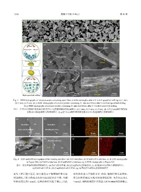
Fig. 3 SEM micrographs of mixed powders containing steel fibers of different lengths after 6+1 h shift-speed ball milling: (a) 1 mm;
(b) 5 mm; (c) 9 mm. (d, e) SEM micrographs of a mixed powder containing 11 mm steel fibers after 6 h of low-speed ball milling.
(f, g) SEM micrographs of a mixed powder containing 11 mm steel fibers after 6+1 h shift-speed ball milling
图 3 含不同长度钢纤维的混合粉末经6+1 h变速球磨后的SEM照片:(a) 1 mm;(b) 5 mm;(c) 9 mm. (d, e)含11 mm钢纤维的混
合粉末6 h低速球磨后的SEM照片. (f, g)含11 mm钢纤维的混合粉末6+1 h变速球磨后的SEM照片
(a) (b) (c) (d)
Steel fiber Cu Steel fiber Cu
Holes and inclusions Bonding interface
10 μm 10 μm 50 μm 50 μm
Cu Fe
(e) (f) (g) (h)
Bonding interface
FeS
Holes and cracks
FeS Cu
Cu 5 μm 2 μm Cu 2 μm S 2 μm
Fig. 4 SEM and EDS micrographs of the bonding interface: (a) Fe/Cu interface; (b) (Cu@Fe)/Cu interface; (c, d) EDS micrographs
in Figure 4(b); (e) FeS/Cu interface; (f) (Cu@FeS)/Cu interface; (g, h) EDS micrographs in Figure 4(f)
图 4 结合界面的SEM和EDS照片:(a) Fe/Cu结合界面;(b) [(Cu@Fe)/Cu]界面结合;(c, d) 图(b)中Cu和Fe元素EDS照片;
(e) FeS/Cu结合界面;(f) (Cu@FeS)/Cu结合界面;(g, h) 图(f)中Cu和S元素的EDS照片
度先下降后趋于稳定. 这可能是由于镀铜钢纤维长度 材料的密度几乎保持不变. 相反,随钢纤维长度增加,
增加降低了粉末的流动从而引起试样密度下降,当钢 复合材料的硬度呈现出快速增加趋势,当其长度到达
纤维长度达到7 mm后,这种影响作用趋于稳定,因此 7 mm后,材料的硬度上升到最大值78 HRB并保持稳定,