
Page 145 - 摩擦学学报2025年第5期
P. 145
第 5 期 许华林, 等: 阶梯螺旋槽端面密封摩擦学性能数值研究 779
d 1 =1 μm d 1 =2 μm d 1 =3 μm d 1 =4 μm d 1 =5 μm d 1 =6 μm
20.0 20.0 20.0 20.0 20.0 20.0
17.5 17.5 17.5 17.5 17.5 17.5
15.0
15.0
15.0
15.0
15.0
15.0
Flat-bottomed y/mm 12.5 y/mm 12.5 y/mm 12.5 y/mm 12.5 y/mm 12.5 y/mm 12.5
10.0
10.0
10.0
10.0
10.0
10.0
7.5
7.5
7.5
7.5
7.5
7.5
5.0
2.5
2.5
2.5
2.5
2.5 5.0 5.0 5.0 5.0 5.0
2.5
0.0 0.0 0.0 0.0 0.0 0.0
15 1719212325 15 1719212325 15 1719212325 15 1719212325 15 1719212325 15 1719212325
x/mm x/mm x/mm x/mm x/mm x/mm
20.0 20.0 20.0 20.0 20.0 20.0
17.5 17.5 17.5 17.5 17.5 17.5
15.0 15.0 15.0 15.0 15.0 15.0
12.5
12.5
12.5
12.5
12.5
12.5
Stepped y/mm 10.0 y/mm 10.0 y/mm 10.0 y/mm 10.0 y/mm 10.0 y/mm 10.0
7.5
7.5
7.5
7.5
7.5
7.5
5.0 5.0 5.0 5.0 5.0 5.0
2.5 2.5 2.5 2.5 2.5 2.5
0.0 0.0 0.0 0.0 0.0 0.0
15 1719212325 15 1719212325 15 1719212325 15 1719212325 15 1719212325 15 1719212325
x/mm x/mm x/mm x/mm x/mm x/mm
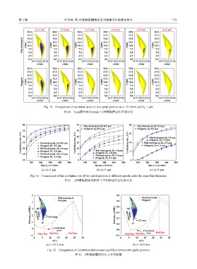
Fig. 10 Comparison of cavitation areas of two spiral grooves at ω=50 r/min and H 0 =1 μm
图 10 1 μm膜厚和50 r/min下2种螺旋槽空化区域对比
40 30 Flat-bottomed, H 0 =0.5 μm 20 Flat-bottomed, H 0 =0.5 μm
Stepped, H 0 =0.5 μm 15 Stepped, H 0 =0.5 μm
Cavitation rate, δ/% 35 Flat-bottomed, H 0 =0.5 μm Cavitation rate, δ/% 25 Cavitation rate, δ/% 10 Flat-bottomed, H 0 =1.5 μm
20
30
Flat-bottomed, H 0 =1.0 μm
Stepped, H 0 =1.0 μm
15
25
Stepped, H 0 =1.5 μm
Stepped, H 0 =0.5 μm
10
20
Flat-bottomed, H 0 =1.0 μm
Stepped, H 0 =1.0 μm
Stepped, H 0 =1.0 μm
15
Flat-bottomed, H 0 =1.5 μm
Flat-bottomed, H 0 =1.5 μm
Stepped, H 0 =1.5 μm 5 Flat-bottomed, H 0 =1.0 μm 5
Stepped, H 0 =1.5 μm
10 0 0
100 200 300 400 500 100 200 300 400 500 100 200 300 400 500
Speed, ω/(r/min) Speed, ω/(r/min) Speed, ω/(r/min)
(a) d 1 =1 μm (b) d 1 =3 μm (c) d 1 =5 μm
Fig. 11 Comparison of the cavitation rate of two spiral grooves at different speeds under the same film thickness
图 11 2种螺旋槽相同膜厚下不同转速时空化率对比
5 0.6
Flat-bottomed Flat-bottomed
4 Stepped 0.5 Stepped
0.4
Pressure, p/MPa 3 2 1 direction r=23.5 mm Pressure, p/MPa 0.3 direction r=22 mm
30°
30°
0.2
Flow
Flow
0 0° Cavitation 0.1 0°
area 0.0 Cavitation
Start line Step line End line Start line Step line area End line
−1 −0.1
0 5 10 15 20 25 30 0 5 10 15 20 25 30
θ/(°) θ/(°)
(a) r=23.5 mm (b) r=22.0 mm
Fig. 12 Comparison of circumferential pressure profiles between two spiral grooves
图 12 2种螺旋槽周向压力分布轮廓