Page 94 - 《爆炸与冲击》2026年第6期
P. 94

第 46 卷           卢毓崟,等: 层理倾角与锚固方式耦合作用下砂岩的动态力学特性                                 第 6 期

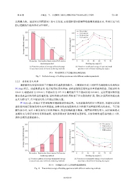
               达到最大值。通过对比不同锚固工况可以发现,虽然锚杆锚固能够降低整体反射能水平,但难以完全消
               除层理倾角引起的各向异性特征。


                                                                       No-anchor
                       225   223.77  212.21                     240    End-anchor
                                                                       Semi-anchor
                      Average reflected energy/J  210  191.74  Reflected energy/J  220
                                                                       Full-anchor


                                                                200
                       195


                       180                            175.66    180
                                                                160
                           No-anchor End-anchor Semi-anchor Full-anchor  0  15  30  45  60   75   90
                                     Anchoring method                        Bedding dip angle/(°)
                           (a) Variation pattern of average reflected energy  (b) Variation in reflected energy of each anchored
                           in specimens under different anchoring methods  specimen with different bedding dip angles

                                             图 9    不同锚固方式下层理试样反射能曲线
                                 Fig. 9    Reflected energy of bedding specimens with different anchoring methods
                2.2.2    透射能变化规律
                   透射能的变化情况反映了岩体内部传递荷载的能力。不同锚固方式下试样平均透射能变化曲线如
               图  10(a) 所示。试验数据表明:随着锚固长度的增加,试样透射能呈现明显的单调递增趋势,无锚试样为
               226.81 J,端锚试样为    229.84 J,半锚试样为     237.15 J,最终提升至全锚试样的          245.84 J。这说明锚固体系能
               够显著改善岩体的荷载传递性能,锚杆的轴向约束作用抑制了径向裂纹的扩展,同时在锚固剂的填充效
               应共同作用下,在全锚固时传力性能达到极大值。
                   图  10(b) 进一步展示了层理倾角对透射能的影响情况。与反射能曲线特征不同的是,各锚固试样的
               透射能均随层理倾角增大而单调递减,这种曲线变化趋势的差异性源于试样破坏模式的改变。当层理
               倾角较小时,试样主要表现为贯穿层理破坏,传递荷载的能力最强。随着层理倾角增大,试样破坏模式
               逐渐转变为沿层理的剪切滑移破坏,裂纹沿弱面扩展的难度显著降低,直接导致传递荷载的能力下降,
               具体表现为透射能减小。


                       245                                      280                        No-anchor
                                                                                           End-anchor
                      Average transmitted energy/J  240  245.84  Transmitted energy/J  240
                                                                                           Semi-anchor
                                                                                           Full-anchor
                                                                260
                       235


                       230
                                     229.84  237.15             220
                       225  226.81                              200
                           No-anchor End-anchor Semi-anchor Full-anchor  0  15  30  45  60   75  90
                                    Anchoring method                         Bedding dip angle/(°)
                          (a) Variation pattern of average transmitted energy  (b) Variation in transmitted energy of each anchored
                           in specimens under different anchoring methods  specimen with different bedding dip angles
                                            图 10    不同锚固方式下层理试样透射能曲线
                               Fig. 10    Transmitted energy of bedding specimens with different anchoring methods


                                                         061421-10
   89   90   91   92   93   94   95   96   97   98   99