
Page 89 - 《爆炸与冲击》2026年第6期
P. 89
第 46 卷 卢毓崟,等: 层理倾角与锚固方式耦合作用下砂岩的动态力学特性 第 6 期
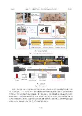
Core-taking
Surface grinding 30° 15° 0°
On-site Reference 90° 75° 60° 45°
sampling T/CSRME
block 001-2019 Ø75 mm×37.5 mm bedding yellow sandstone
Anchoring agent Bolt material Drill
Mass ratio of
curing agent to
colloid 1∶2 4.5 mm
2 h initial curing
Curing Epoxy Ø3 mm Q235 screw
agent resin
Open-hole specimen
Injecting different doses of
48 h fully anchored epoxy resin
15% anchorage length 50% anchorage length 95% anchorage length
End-anchor specimens Semi-anchor specimens Full-anchor specimens
Loadable specimen
图 3 锚固试样制备流程
Fig. 3 Anchorage specimen preparation process
Gas chamber Momentum trap
Spindle bullet Input bar Transmission bar
θ
High-pressure Trigger gear Computer High dynamic Sample
cylinder post-processing strain indicator
图 4 试验设备
Fig. 4 Test equipment
根据一维应力波理论,在岩样破坏前其两端要达到应力平衡状态,所得的试验数据才是真实有效
的。采用厚度为 1.5 mm、直径为 30 mm 的圆形橡胶片波形整形器,通过调整入射波形,可以有效解决试
件内部应力不均匀的问题,实现试件近似恒应变率变形,减少应力波频散现象,从而提高试验结果的准
确性和可靠性。图 5 为岩样破坏时入射、反射、透射应力波以及入射、反射应力叠加形成的波形图,可
以看出,岩样破坏时入射应力、反射应力叠加形成的波形与透射应力近似相等,表明岩样两端始终保持
动态应力平衡,波形表现为半正弦波,保证了试验数据的有效性。
061421-5