Page 92 - 《爆炸与冲击》2026年第5期
P. 92

第 46 卷             冯    彬,等: 基于图神经网络的可燃气体泄漏扩散预测方法                               第 5 期

                2    数据集的建立


                2.1    数值模型的建立与验证
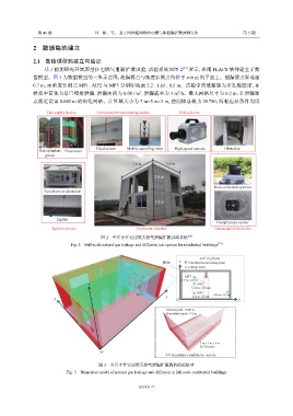
                   基于前期研究开展原型住宅燃气泄漏扩散试验,试验系统如图                            2 [39]  所示,采用  FLACS  软件建立了数
               值模型。图     3 为数值模型的三维示意图,泄漏源点与浓度监测点均位于                         x=6 m  的平面上。泄漏源点距地面
               0.7 m,而浓度监测点      MP1、MP2   与  MP3  分别距地面     2.2、1.65、0.5 m。试验中的泄漏源为多孔橡胶球,在
                                                          2
                                                                         3
               模拟中简化为单口喷射泄漏,泄漏面积为                  0.001 m ,泄漏速率为     3 m /h。最大网格尺寸为         0.2 m,在泄漏源
               点附近设置     0.045 m  的细化网格。计算域大小为            7 m×5 m×3 m,控制体总数为       28 750,所有边界条件均设
                    Gas supply device    Concentration monitoring device  Video device


                 Gas cylinders  Flowmeter  Fixed sensor  Mobile sampling robot  High-speed camera  Obstacles
                   group
                                                       7.0 m        5.0 m

                                                                3.0 m

                                                                                        Data collection systems
                   Synchronous detonator
                                                                3.0 m


                        Lighter
                                                                                         Overpressure sensor
                      Ignition device                   Explosion chamber               Data acquisition device

                                          图 2    全尺寸住宅建筑天然气泄漏扩散试验系统          [39]
                              Fig. 2    Full-scale natural gas leakage and diffusion test system for residential buildings [39]

                                                                                  x=6 m, plane
                                                                   Hole   z  Concentration measuring point
                                                                             Leakage point

                                                                            MP1
                                                                          (1.4 m, 2.2 m)
                                     z                                           MP2
                                                                               (1.4 m, 1.65 m)
                                                                                 MP3
                                                                                        (4.8 m, 0.7 m)
                                                                    x          (1.4 m, 0.5 m)
                       y                                                 O                        y
                                                                     Refined grids : 0.045 m
                                                                     Non-refined grids : 0.2 m


                                                                                  7 m×5 m×3 m
                                                                                  28 750 cells
                                          O
                                                                    All boundary conditions: nozzle
                                         图 3    全尺寸住宅建筑天然气泄漏扩散数值模拟模型
                            Fig. 3    Numerical model of natural gas leakage and diffusion in full-scale residential buildings


                                                         051431-7
   87   88   89   90   91   92   93   94   95   96   97