Page 131 - 《爆炸与冲击》2026年第2期
P. 131

µ฀ε
                                                    7.182×10
                                                                                                  9.057×10
                                                    5.586×10
                                                                                                        −9
                                                    3.990×10                                      1.174×10 −8
                                                                                                  6.375×10
                                                                                                        −9
                                                    2.394×10                                      3.692×10 −9
                                                    7.985×10 2                                    1.010×10 −9
                                                    5.262×10 −1                                  −3.316×10 −10
                    第 46 卷             白春玉,等: 不同垂向速度下翼身融合民机机体的坠撞响应                                  第 2 期
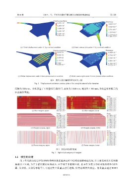
                   (a) Global displacement under −2.5            (b) Strain contour plot under −2.5

                                                 Displacement/mm                                Strains/µ฀ε
                                                    2.879×10 3                                    5.089×10 −9
                                                    2.240×10 3                                    3.925×10 −9
                                                    1.600×10 3                                    2.761×10 −9
                                                    9.603×10 2                                    1.597×10 −9
                                                    3.207×10 2
                                                    8.642×10 −1                                   4.337×10 −10
                                                                                                 −1.481×10 −10


                   (c) Global displacement under +1.0g overload condition  (d) Strain contour plot under +1.0g overload condition
                                                 Displacement/mm                                Strains/µ฀ε
                                                    6.454×10                                      6.088×10 −9
                                                    5.021×10                                      4.726×10 −9
                                                    3.589×10                                      3.364×10 −9
                                                    2.157×10                                      2.001×10 −9
                                                    7.244                                         6.393×10 −10
                                                    8.268×10 −2                                  −4.178×10 −11


                 (e) Global displacement under 2 times pressurization condition  (f) Strain contour plot under 2 times pressurization condition
                                              图 4    迭代完成后整机位移及应变云图
                                Fig. 4    Displacement and strain contour plots of the complete aircraft after iteration

               间隔为   500 mm。全机设置了        3  对登机门/服务门,高度为         2 000 mm,宽度约    1 300 mm,均布置在客舱三角
               区前缘位置处。

                                                    Strain                                       Strain

                                                     1.000×10 −9                                  1.000×10 −9
                                                     4.581×10 −6                                  5.020×10 −6
                                                     9.126×10 −6                                  1.004×10 −5
                                                     1.374×10 −5                                  1.506×10 −5
                                                     1.823×10 −5                                  2.008×10 −5
                                                     2.290×10 −5                                  2.510×10 −5
                                                     2.748×10 −5                                  3.012×10 −5
                                                     3.206×10 −5 −5                               3.514×10 −5 −5
                              (a) Skin margins, upper  3.664×10 −5        (b) Skin margins, lower  4.016×10 −5
                                                                                                  4.518×10
                                                     4.122×10
                                                    Strain                                       Strain
                                                     1.400×10 −8                                  1.000×10  −8
                                                     2.238×10 −4 −4                               1.957×10  −4 −4
                                                     4.475×10                                     3.913×10 −4
                                                     6.713×10 −4                                  5.869×10
                                                     8.950×10 −4                                  7.826×10  −4
                                                     1.119×10 −4                                  9.782×10  −4
                                                     1.343×10 −4                                  1.174×10  −3
                                                     1.566×10 −4 −4                               1.370×10  −3 −3
                             (c) Stringer margins, upper  1.790×10 −2    (d) Stringer margins, lower  1.565×10  −3
                                                     2.014×10
                                                                                                  1.761×10
                                                    Strain                                       Strain
                                                     1.000×10 −9                                  4.000×10  −9
                                                     2.394×10 −4                                  2.394×10 −4
                                                     4.787×10 −4                                  4.787×10 −4
                                                     7.181×10 −4                                  7.181×10  −4
                                                     9.574×10 −4                                  9.574×10  −4
                                                     1.197×10 −3                                  1.197×10  −3
                                                     1.436×10 −3                                  1.436×10  −3
                                                     1.675×10 −3                                  1.675×10 −3 −3
                                                     1.915×10 −3                                  1.915×10
                             (e) Frame margins, upper  2.154×10 −3        (f) Frame margins, lower  2.154×10  −3
                                                   图 5    优化后的部件裕度
                                               Fig. 5    Optimized component margins
                1.2    模型的处理
                   由于本文的目的是评估           BWB  构型民机在坠撞过程中结构的整体响应情况,且主要变形发生在客舱
               地板以下区域,为了节省计算时间和成本,对于处于非破坏区域、且不作为受力分析对象的部件(如外
               翼、发动机、头顶行李箱等),可通过集中质量点进行建模,仅考虑其惯性效应。各质量点通过                                            RBE3

                                                         023103-5
   126   127   128   129   130   131   132   133   134   135   136