
Page 147 - 《爆炸与冲击》2025年第12期
P. 147
第 45 卷 王可慧,等: 两种材料结构弹体高速侵彻钢筋混凝土靶实验研究 第 12 期
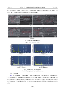
凝土中的典型元素)含量明显增高,而 Fe 元素含量明显降低,说明弹靶材料在高温高压作用下发生了氧
化和扩散,少量混凝土靶板颗粒在侵彻过程中熔融在弹体表面。
(a) (b) (c) (d)
Melt
Melt+Plastic flow Ploughing
Furrow
Furrow
Point A Point B Point C Point D
50 μm 50 μm 50 μm 50 μm
Projectile 1
(e) Melt (f) (g) (h)
Ploughing
Material Ploughing
Furrow Melt Particle accumulation
Point A Point B Point C Point D
50 μm 50 μm 50 μm 50 μm
Projectile 2
图 10 弹体 1 和 2 的表面微观形貌
Fig. 10 SEMs of projectiles 1 and 2
6 Fe Element Mass fraction/% 谱图26 6 Fe Element Mass fraction/%
Counts per second/eV 4 2 C O Fe Ni Si Mg 48.16 Counts per second/eV 4 2 C O Cr Fe Co Ni Mo Cr Co Ni Mo 48.63
C
39.10
21.59
C
O
O
8.71
9.71
Co
0.45
9.36
Cr
2.31
0.90
Si
Fe
Fe
1.27
0.93
Cr
Mg
Ni
Ni
0.75
8.13
Cr
Total
Ni
Total
Cr
Mo
Ni Ni
4
6
0
2
10
8
10
8
Energy/keV 12 14 100 16 18 20 0 2 4 6 Energy/keV 12 14 100 16 Mo 18 20
(a) Point B of projectile 1 (b) Point B of projectile 2
8 6 Fe Element Mass fraction/% 6 Fe Element Mass fraction/%
Counts per second/eV 4 2 C Mn Fe Mn 51.66 Counts per second/eV 4 2 C Ni Co Ni Co S 41.13
34.91
C
C
41.23
O
7.07
5.00
O
0.26
Si
0.30
Si
0.62
Fe
Fe
Cr
0.68
1.82
Cr
0.81
O
Ni
6.33
O
Cr
Fe
7.92
Co
0.25
Ca
Total
100
Total
0 Cr Si 2 4 Cr Mn 6 Fe 8 10 12 14 16 18 20 0 Ca Si 2 S Ca 4 Cr 6 8 Ni 10 12 14 100 16 18 20
Energy/keV Energy/keV
(c) Point C of projectile 1 (d) Point C of projectile 2
图 11 不同测点处弹体 1 和 2 的 EDS 谱图
Fig. 11 EDSes of projectiles 1 and 2 at different points
(2)弹体截面分析
图 12 为 2 发弹体的截面显微组织形貌。高速侵彻过程中,弹体与靶相互作用产生的热量和冲击压
力作用于弹体表面。由于受到的热影响程度和冲击压力不同,弹体在不同区域呈现出不同的形貌。弹
体头部在外边界呈锯齿状,说明在犁切和碰撞作用下,弹头区域承受长时间的侵蚀和挤压作用,最终
在弹头表面形成了明显的锯齿状脱落。对比发现,30CrMnSiNi2MoVE 弹头的脱落现象比 DT1900 更加
严重。
123301-7