
Page 203 - 卫星导航2021年第1-2合期
P. 203
Wang et al. Satell Navig (2021) 2:4 Page 3 of 9
pseudo-random sequence c(k) . Te output signal R out (t)
is
R out (t) = R in (t)e −jϕ(t) (4)
where e −jϕ(t) is phase compensation factor.
Binary phase hopping based SCA technique
Te commonly used SCA technique inserts unpredict-
able authentication chips into the public spreading code.
Tis paper proposes an SCA technique that modulates
authentication information on the signal phase.
Signal structure
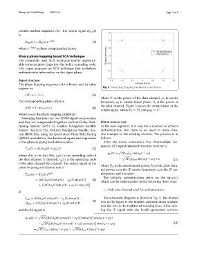
Te phase hopping sequence c(k) is binary and its value
is given by Fig. 3 Binary phase hopping modulation constellation
(5)
c(k) ∈ {−1, 1}
where P 1 is the power of the data channel, ω c is carrier
Te corresponding phase ofset is frequency, ϕ 0 is carrier initial phase, P 2 is the power of
the pilot channel. Figure 3 shows the constellation of the
(6)
ϕ(k) ∈ {−ϕ PH , ϕ PH }
output signal, where P 1 = P 2 , and ϕ PH = 5 .
◦
where ϕ PH is the phase hopping amplitude.
Assuming that there are two GNSS signal components,
and they are compounded together, such as Global Posi- SCA at receiver end
tioning System (GPS) L5, Galileo Navigation Satellite In the user segment, it is easy for a receiver to achieve
System (Galileo) E5a, BeiDou Navigation Satellite Sys- authentication, and there is no need to make mas-
tem (BDS) B2a, using the Quadrature Phase Shift Keying sive changes to the existing receiver. Te process is as
(QPSK) modulation. Te baseband equivalent expression follows.
of the phase hopping modulation unit is After the down conversion, the Intermediate Fre-
quency (IF) signal obtained from the receiver is
T in (t) = d(t)c d (t) + jc p (t) (7)
s IF (t) = 2P r1 I out cos(ω i t + ϕ i )
where d(t) is the data bits, c d (t) is the spreading code of
the data channel (I channel), c p (t) is the spreading code − 2P r2 Q out sin(ω i t + ϕ i )+n (11)
of the pilot channel (Q channel). Te output signal of the
phase hopping modulation unit is where P r1 is the data channel power, P r2 is the pilot chan-
nel power, ω i is the IF carrier frequency, ϕ i is the IF car-
T out (t) = T in (t)e jϕ(t) rier phase, and n is noise.
Te identity authentication relies on the sin ϕ(t) ,
= d(t)c d (t) cos ϕ(t) − c p (t) sin ϕ(t) (8)
which can be implemented in the following three ways.
+ j d(t)c d (t) sin ϕ(t) + c p (t) cos ϕ(t)
1. Only pilot channel used for authentication
if
I out = d(t)c d (t) cos ϕ(t) − c p (t) sin ϕ(t) Te schematic diagram is shown in Fig. 4. Te dashed
(9) box in the fgure is the identity authentication module,
Q out = d(t)c d (t) sin ϕ(t) + c p (t) cos ϕ(t)
and the rest is the traditional tracking loop. After mix-
and the RF signal is ing the IF signal with the locally generated carriers,
s PH (t) = 2P 1 d(t)c d (t) cos ϕ(t) − c p (t) sin ϕ(t) cos(ω c t + ϕ 0 )
(10)
− 2P 2 d(t)c d (t) sin ϕ(t) + c p (t) cos ϕ(t) sin(ω c t + ϕ 0 )
= 2P 1 I out cos(ω c t + ϕ 0 ) − 2P 2 Q out sin(ω c t + ϕ 0 )