Page 150 - 摩擦学学报2025年第8期
P. 150

1248                                   摩擦学学报(中英文)                                        第 45 卷


               (a)  1) Coating photoresist, soft bake  4) 2 nd  masked irradiation  (b)  (c)
                             SU-8
                             Si wafer
                  2) Masked irradiation  5) Development
                             Mask
                  3) Coating new photoresist layer  6) Soft molding, demolding

                                                                          5 μm                500 μm

               (d)                    Peeling-off direction  (e)                    (f)


                 Etched Si  Pouring PUA  UV exposure &  Angled nanostructures  ~60°  Stooped nanohairs  Vertical nanohairs
                 master                 detachment  with high A.R.           2 μm                    2 μm

               (g)                    (h)     Magnetic induced  (i)  s-FGPs           (j)
                                                                                5 μm
                                                                                                       Layer 1
                                                                                                       Layer 2
                                                                                                       Layer 3
                                                           Decrease                                    Layer 4
                                                                                                       Layer 5
                             750 μm                          10 μm              5 μm                   10 μm

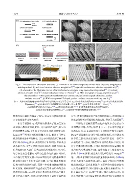
               Fig. 6    The construction of complex structures: (a) schematic of the fabrication process of multi-level structures using physical
                                                               2 [21]                                 [80]
                 molding method; (b) multi-level structure adhesive array(8N/cm ) ; (c) multi-level structure adhesive array (600 mN) ;
                                                                                            [21]
                  (d) schematic of the fabrication process of inclined adhesive structures using physical molding method ; (e) inclined
                                  2 [21]                        2 [20]                                [81]
                 adhesive array (21 N/cm ) ; (f) inclined adhesive array (11 N/cm ) ; (g) SEM micrograph of wedge-shaped structure ;
                      (h) schematic of vertical gradient modulus structure construction;(i) SEM micrograph of inclined gradient
                                    [82]                                                         [83]
                       modulus structure ; (j) SEM micrograph of T-shaped gradient modulus structure mimicking tree frog
             图 6    复杂结构的构建:(a)物理成型法多层结构制备过程示意图;(b)多层结构胶粘剂阵列(8 N/cm ) ;(c)多层结构胶粘剂阵
                                                                                        2 [21]
                               [80]
                       列(600 mN) ;(d)物理成型法倾斜胶粘剂结构制备过程示意图 ;(e)倾斜胶粘剂阵列(21 N/cm ) ;
                                                                      [21]
                                                                                               2 [21]
                                                                   [81]
                                              2 [20]
                         (f)倾斜胶粘剂阵列(11 N/cm ) ;(g)楔形结构SEM照片 ;(h)垂直梯度模量结构构建示意图;
                                 (i)倾斜梯度模量结构SEM照片 ;(j)仿树蛙T型梯度模量结构SEM照片                 [83]
                                                        [82]
            纤维的法向黏附力提高了70%,这主要与接触面积增                           应性,从而使接触界面产生较好的附着力;而逐渐硬化
                                                                                                          [90]
            大导致范德华力增大有关.                                       的根部能够保证纤维的结构稳定性,保证了其耐用性 .
                相比于倾斜结构,楔形结构表现出了更加优异的                              早期的功能梯度模量结构的构筑方式包括离心
            黏附各向异性和耐疲劳性,并且楔形结构是1类天然                            和逐层沉积等,但其材料尺寸较大且存在非连续梯度
            的梯度模量结构,更加接近壁虎刚毛末端的真实情况.                           结构的问题,这会导致材料的长时使用性能受到影响.
                     [89]
            Parness等 利用双掩模倾斜曝光技术,制造了可重复                        Dong等通过磁铁在空间中施加梯度磁场,预分散在流
            使用的楔形腔体阵列模板,并基于硅橡胶成型了楔形黏                           体中的二氧化硅表面功能化的纳米四氧化三铁填料
            附阵列,如图6(g)所示. 其黏附具有各向异性,并表现出                       在磁场作用下形成了梯度分布的共混效果,固化后固

            动态黏合力,可重复使用超过30 000次. 其最大法向黏                       定了纳米填料的位置. 其构筑的功能梯度模量微柱的
                             2                           2
            附力达到0.26 N/cm ,最大切向黏附力达到1.59 N/cm .                底座到尖端模量相差6倍,成功模仿了生物黏性刚毛
            尽管在过去的很长时间里仿生黏合剂的表面图案化                             结构,如图6(h)所示. 通过改变固化成型模具,Wang等               [82]
            工作得到了充分发展,但表面图案化结构的柔顺性和                            进一步制备了倾斜功能梯度模量微柱(S-FGP),如图6(i)
            稳定性仍是1个自相矛盾的问题. 这个问题是不能通                           所示. S-FGP具备强剪切、耐用、各向异性和对不同粗
            过表面结构设计解决的,而进一步对生物接触结构的                            糙度界面的自适应黏附能力. T形结构尖端能够提供
            研究发现,树蛙脚趾垫和壁虎刚毛等生物结构都是梯                            更大的接触面积,同时能够大幅度降低接触应力,并
                                                                                   [83]
            度模量的结构,其中壁虎刚毛基部到毛尖的杨氏模量                            防止裂纹的产生. Liu等 受树蛙刚毛结构的启发,用
            最大差异达20倍. 这种梯度结构保留了柔性尖端的顺                          离心法构筑了梯度模量微柱结构并将T形尖端移植到
   145   146   147   148   149   150   151   152   153   154   155