Page 84 - 《摩擦学学报》2021年第1期
P. 84

第 1 期             王松, 等: 髓核固定/滑动型人工颈椎间盘应力特征对比及关节面摩擦学优化设计                                      81


                  A: Static structural                               A: Static structural
                  Total deforrnation 2                               Total deforrnation 2
                  Type: Total deformation                            Type: Total deformation
                  Unit: mm                                           Unit: mm
                  Time: 1                                            Time: 1
                  2020-3-24 11:52                                    2020-3-24 11:53
                    252.09 Max                                         252.09 Max
                    229.85                                             229.85
                    207.62                                             207.62
                    185.39                                             185.39
                    163.15                                             163.15
                    140.92                                             140.92
                    118.69                                             118.69
                    96.451                                             96.451
                    74.217                                             74.217
                    51.983 Min                                         51.983 Min
                                                                                                   z
                              0        10 mm        x                            0        10 mm  x
                                   5            z  y                                  5             y
                                  (a1)                                                (a2)
                  A: Static structural                               A: Static structural
                  Total deforration 3                                Total deforration 3
                  Type: Total deforrmation                           Type: Total deforrmation
                  Unit: mm                                           Unit: mm
                  Time: 1                                            Time: 1
                  2020-3-24 11:52                                    2020-3-24 11:53
                    209.33 Max                                         209.33 Max
                    186.3                                              186.3
                    163.26                                             163.26
                    140.23                                             140.23
                    117.2                                              117.2
                    94.162                                             94.162
                    71.128                                             71.128
                    48.094                                             48.094
                    25.06                                              25.06
                    2.026 6 Min                                        2.026 6 Min
                                                                                                    z
                              0        10 mm       x                             0        10 mm  x
                                  5               y                                   5             y
                                  (b1)                                                (b2)
                  A: Static structural                               A: Static structural
                  Total deformation 4                                Total deformation 4
                  Type: Total deformation                            Type: Total deformation
                  Unit: mm                                           Unit: mm
                  Time: 1                                            Time: 1
                  2020-3-24 11:52                                    2020-3-24 11:53
                   254.6 Max                                           254.6 M4iax
                   231.81                                              231.81
                   209.02                                              209.02
                   186.23                                              186.23
                   163.44                                              163.44
                   140.64                                              140.64
                   117.85                                              117.85
                   95.064                                              95.064
                   72.273                                              72.273
                   49.482 Min                                          49.482 Min
                                                                                                   z
                              0        10 mm       x                             0       10 mm   x
                                                z                                                   y
                                  5              y                                    5
                                  (c1)                                                (c2)

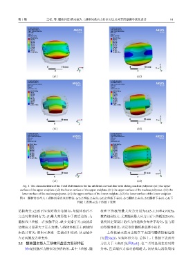
               Fig. 4  The characteristics of the Total Deformation for the artificial cervical disc with sliding nucleus pulposus:(a1) the upper
             surface of the upper endplate,(a2) the lower surface of the upper endplate,(b1) the upper surface of the nucleus pulposus,(b2) the
               lower surface of the nucleus pulposus,(c1) the upper surface of the lower endplate,(c2) the lower surface of the lower endplate
             图 4    髓核滑动型人工颈椎间盘总变形特征:(a1)上终板上表面,(a2)上终板下表面,(b1)髓核上表面,(b2)髓核下表面,(c1)下
                                                 终板上表面,(c2)下终板下表面

            结构有关;(2)前后呈现对称分布倾向,与假体前后不                          核和下终板的最大应力分别为6.65、1.36和4.9 MPa,
            完全对称结构有关;(3)最大变形集中于前后边缘,与                          数值相差较大,尤其髓核最大应力只有上终板的20.5%,
            髓核和上终板二者接触不良、缺少支撑有关;(4)前后                          说明固定型设计的应力传递和分布并不均匀,但与滑

            边缘应力显著大于左右边缘,与假体终板左右两侧倒                            动型假体相比,固定型的髓核承载要小很多.
            齿设计有关,倒齿可承受一定载荷和变形,从而减少                                上终板最大应力出现在下表面与髓核接触边缘
            左右两侧应力和变形.                                         [见图5(a2)],呈现环形分布. 总体上,上终板下表面应
            2.2    髓核固定型人工颈椎间盘应力变形特征                           力要大于上表面[见图5(a1)],但二者均呈现左右对称
                图5是接触应力特征的分析结果,其中上终板、髓                         分布,且后端应力相对前端略大,该结果与滑动型相
   79   80   81   82   83   84   85   86   87   88   89