Page 83 - 《摩擦学学报》2020年第6期
P. 83

766                                     摩   擦   学   学   报                                 第 40 卷

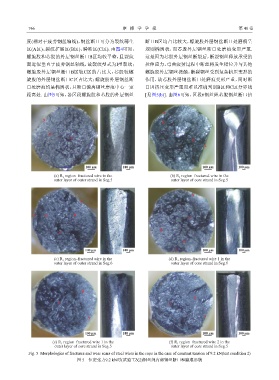
            度(相对于疲劳钢丝轴线),钢丝断口可分为裂纹萌生                           断口B区均占比较大,螺旋股外层钢丝断口处磨痕呈
            区(A区)、裂纹扩展区(B区)、瞬断区(C区). 由图4可知,                    规则椭圆状,而芯股外层钢丝断口处磨痕变形严重.
            螺旋股和芯股的外层钢丝断口B区均较平整,且裂纹                            这是因为芯股外层钢丝断裂后,断裂钢丝释放承受的
            面近似垂直于疲劳钢丝轴线,故裂纹型式为I型裂纹;                           拉伸应力,弯曲疲劳过程中断丝将发生错位并与其他
            螺旋股外层钢丝断口B区较C区的占比大,芯股较螺                            螺旋股外层钢丝接触,断裂钢丝受到复杂挤压变形的
            旋股的外层钢丝断口C区占比大;螺旋股外层钢丝断                            作用,故芯股外层钢丝断口处磨痕变形严重,同时断
            口处磨痕均呈椭圆状,且断口偏离钢丝磨痕中心一定                            口因挤压变形严重而难以准确判别B区和C区分界线
            距离处. 由图5可知,各区段螺旋股和芯股的外层钢丝                          [见图5(b)]. 由图6可知,区段6钢丝绳芯股钢丝断口挤


                                                                      A
                   A
                                                                      B

                      B                                                    C
                               C
                                                                                   B
                                                                                        A


                                      100 μm         100 μm                            100 μm          100 μm
                        (a) R 2  region–fractured wire in the             (b) R 2  region–fractured wire in the
                        outer layer of outer strand in Seg.5              outer layer of core strand in Seg.5


                                                                                   A
                                   A


               A    B            B
                                                                                  C

                                                                     B
                          C
                                                                               B
                                     100 μm          100 μm                 A          100 μm          100 μm
                        (c) R 1  region–fractured wire in the            (d) R 1  region–fractured wire 1 in the
                        outer layer of outer strand in Seg.6              outer layer of core strand in Seg.6


                                    B
                                                                                    B
                          C
                                                                         C

                                                                                        A
                                      A

                                     100 μm          100 μm                            100 μm          100 μm
                       (e) R 1  region–fractured wire 1 in the           (f) R 1  region–fractured wire 2 in the
                        outer layer of core strand in Seg.5               outer layer of core strand in Seg.5

             Fig. 5  Morphologies of fractures and wear scars of steel wires in the rope in the case of constant tension of 9.2 kN(test condition 2)
                                  图 5    恒定张力9.2 kN时(试验工况2)钢丝绳内部钢丝断口和磨痕形貌
   78   79   80   81   82   83   84   85   86   87   88