
Page 130 - 《摩擦学学报》2020年第4期
P. 130
540 摩 擦 学 学 报 第 40 卷
表 1 密封环和密封介质的物理性能 [20] 构内部进行网格局部加密,进行了网格无关性验证,
Table 1 Material properties of the sealing ring and 结果详见表3. 可以看出,网格数量的不同会对计算结
sealing medium
果产生一定的影响,若以最后1组网格为对比基准,其
3
Materials k/(W/m·K) ρ/(kg/m ) c/(J/kg·K) μ/(Pa·s)
他组不同网格数与基准之间存在的偏差,综合计算精
17-4PH(Stator) 18 7 900 419 -
Carbon graphite(Rotor) 14 1 825 670 - 度和计算时间的考虑,本文中采用的网格数为507 342.
0.29 1 018.42 3 200 0.007 05
C 3 H 8 O 2
表 3 网格无关性验证
Table 3 Grid independence verification
Seal face
Number of grids Face average temperature/K Deviation/%
99 761 334.184 72 5.35%
310 325 331.741 1.13%
507 342 331.228 49 0.25%
709 479 331.125 32 0.07%
913 234 331.084 81 -
Y
Z X 2 边界条件及计算方法确定
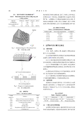
Fig. 3 Schematic diagram of the textured torus
2.1 基本假设
图 3 织构环面示意图
不失一般性,为简化计算,在满足计算精度的前
A 提下,作出如下假设:
(1) 远离密封端面的表面温度与密封流体来流温
l 2 度相同,如图2中的W8、W9表面等;
(2) 由于密封端面附近的对流换热系数远大于密
封环其他部位,故假设远离密封端面的表面为绝热面;
(3) 由于本案例泄漏小于有关标准,因此忽略因
介质泄漏导致热量被带走的情况,即热量全部由冷却
α 液带走;
(4) 假设动环外周表面不存在滑移现象,即外周
(a) Circumferential parameter
面上某点处流体与该点面的速度相等;
d l 1
(5) 不考虑冲洗介质的物性随温度变化的影响,
h
不考虑热辐射的影响,不考虑流体相态变化.
2.2 边界条件
l 2
依据密封实际操作条件设工作介质以0.2 m/s的
(b) A section parameter
速度进入密封腔体,入口温度为25 ℃,密封腔体内壁
Fig. 4 Diagram of related parameters
温度取入口温度(25 ℃),出口压力为0.8 MPa,其他边
图 4 相关参数设置图
界条件详见表4.
表 2 参数符号
Table 2 Parameter symbol 表 4 边界条件
Table 4 Boundary conditions
Related Value
Definition
parameters range W1 Velocity inlet W7 Pressure outlet
d/mm Diameter (Texture circumcircle diameter) 0.9 W2,W8~W9 Isothermal boundary W10~W13 Coupling surface
l 1 /mm First line texture distance from the end face 1.2 W3~W6 Adiabatic boundary WS Heat generating surface
l 2 /mm Line spacing between textures 0.6~1.3
h/mm Texture depth 0.03~0.18
2.3 计算方法与计算流程
n/min Rotating speed 1 800
Wing distance (the angle of the adjacent texture 雷诺数是1种流体密度、速度和特征长度以及流
α/(°) 2~6
of the same row) 体动力黏度的函数,表征流体流动情况;鉴于密封腔