
Page 45 - 《爆炸与冲击》2026年第6期
P. 45
第 46 卷 杜晓庆,等: 接触爆炸作用下钢桁梁桥的破坏模式与剩余承载力 第 6 期
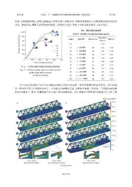
程中,无损结构两侧上弦杆全截面进入塑性而发生屈曲变形,导致最终破坏时下方桥面板出现两处高应
力区。相较而言,爆炸后桥梁结构仅损伤上弦杆发生屈曲,导致下方桥面板形成单一高应力区。
表 8 剩余承载性能结果
1 200 Ⅱ Ⅲ
Table 8 Results of residual bearing capacity
Ⅳ 工况编号 爆炸位置 爆炸当量/kg 剩余承载力/ 损伤因子
Bearing capacity/(MN·m) 800 Ⅰ Ⅰ Ⅲ Ⅳ S0 S0 a—单点爆炸 100 (MN·m) 0.298
1 000
Ⅱ
1 169
600
S1
821
S1
400
958
S3
200 S2 S2 b—单点爆炸 100 1 142 0.180
c—单点爆炸
S3
0.023
100
S4
S4 d—单点爆炸 100 1 140 0.025
0 100 200 300 400 500
Vertical displacement/mm S5 a—单点爆炸 25 1 066 0.088
S6 a—单点爆炸 50 986 0.157
图 16 不同位置爆炸后钢桁梁桥剩余承载性能
S7 a—单点爆炸 150 779 0.334
Fig. 16 Residual bearing capacities of the steel truss
S8 a、f—两点爆炸 100 679 0.419
girder bridge after explosions
at different locations S9 a、e—两点爆炸 100 802 0.314
S10 a、e、f—三点爆炸 100 641 0.452
图 17(b) 对比分析了 S0 与 S1 结构在承载力分析中时刻Ⅱ~Ⅳ的等效塑性应变分布图。其中时刻
Ⅱ~Ⅳ对应于图 16 中相应时间点。在承载力达到峰值之前,全桥处于弹性工作阶段。当承载力到达峰
值时(时刻Ⅱ)工况 S1 在爆炸破口处出现了明显的塑性区。进入承载力下降阶段(时刻Ⅲ)后,2 种工况
Mises stress/MPa
435.0
S0 S1
391.5
Ⅰ Ⅰ 348.0
304.5
261.0
Ⅱ Ⅱ
217.5
174.0
Ⅲ Ⅲ
130.5
87.0
Ⅳ Ⅳ
43.5
Yield point
0
Upper chord Upper chord Upper chord
first fracture location second fracture location single fracture location
(a) Mises stress
Effective plastic strain
Ⅱ 061412-14
Ⅰ Ⅱ
Ⅲ Ⅲ
Ⅳ Ⅳ