Page 153 - 《爆炸与冲击》2026年第4期
P. 153

第 46 卷            刘天豪,等: 落石冲击下地面混凝土垫层对埋地管道的防护作用                                 第 4 期

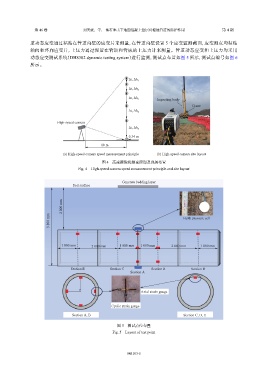
               道动态应变通过粘贴在管道内壁的应变片来测量,在管道内壁设置                               5  个应变监测截面,应变测点均粘贴
               轴向和环向应变片,土压力通过埋置在管顶和管底的土压力计来测量。管道动态应变和土压力均采用
               动态应变测试系统(DH8302 dynamic testing system)进行监测,测试点布置如图                  5  所示,测试点编号如图        6
               所示。


                                                          Δt, Δh 1

                                                          Δt, Δh 2
                                                                       Impacting body
                                                          Δt, Δh 3
                                                                                      Crane
                                                          Δt, Δh 4
                          High-speed camera

                                                          Δt, Δh 5
                                                                                 High speed camera
                                                          0.34 m
                                              10 m
                             (a) High-speed camera speed measurement principle  (b) High-speed camera site layout
                                              图 4    高速摄像机测速原理及现场布置
                                    Fig. 4    High-speed camera speed measurement principle and site layout


                                                       Concrete bedding layer
                                 Soil surface

                             2 000 mm


                       3 800 mm                                                   Earth pressure cell


                            1 000 mm      2 000 mm    1 000 mm  1 000 mm     2 000 mm     1 000 mm


                                Section E         Section C         Section B         Section D
                                                           Section A


                                                                Axial strain gauge


                                                   Cyclic strain gauge
                                 Section A, B                                     Section C, D, E


                                                     图 5    测试点位布置
                                                   Fig. 5    Layout of test point


                                                         045103-5
   148   149   150   151   152   153   154   155   156   157   158