
Page 9 - 摩擦学学报2025年第9期
P. 9
第 9 期 冯芸, 等: G20Mn5QT铸钢激光熔覆316L涂层微动摩擦磨损特性研究 1263
1.0 Substrate-10 μm 1.0 Cladding layer-10 μm
0.9 Substrate-20 μm 0.9 Cladding layer-20 μm
0.8 Substrate-40 μm 0.8 Cladding layer-40 μm
Friction coefficient 0.6 Friction coefficient 0.6
0.7
0.7
0.5
0.5
0.4
0.4
0.3
0.2 Average friction coefficient=0.411 0.3 Average friction coefficient=0.406
0.2
Average friction coefficient=0.647
Average friction coefficient=0.612
0.1 Average friction coefficient=0.675 0.1 Average friction coefficient=0.728
0.0 0.0
1 10 100 1 000 10 000 15 000 20 000 1 10 100 1 000 10 000 15 000 20 000
Number of cycle Number of cycle
(a) Substrate (b) Cladding layer
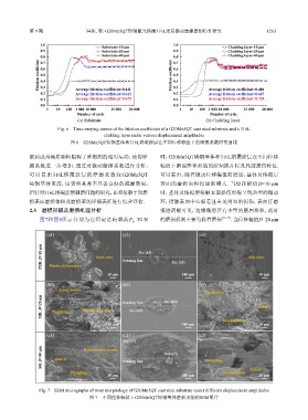
Fig. 6 Time-varying curves of the friction coefficient of a G20Mn5QT cast steel substrate and a 316L
cladding layer under various displacement amplitudes
图 6 G20Mn5QT铸钢基体和316L熔覆涂层在不同位移幅值下的摩擦系数时变曲线
磨屑成为硬质颗粒阻碍了摩擦副的相对运动,使得摩 时,G20Mn5QT铸钢基体和316L熔覆涂层在不同位移
擦系数进一步增加. 通过对微动摩擦系数进行分析, 幅值下磨痕整体形貌的SEM照片以及局部损伤特征.
可以看出316L熔覆涂层的摩擦系数较G20Mn5QT 可以看出,随着微动位移幅值的增加,基体及熔覆层
铸钢基体更高,这表明其并不具备良好的减摩效果, 表面的磨损面积均逐渐增大. 当位移幅值D=10 μm
但针对316L熔覆涂层耐磨问题的研究,还须依赖于对磨 时,基体及熔覆层接触表面损伤形貌呈现典型的微动
损表面磨损体积及磨损率的详细表征进行综合评估. 环,接触表面中心黏着且未见明显的损伤,表面打磨
2.3 磨损形貌及磨损机理分析 痕迹清晰可见,边缘微滑区有少量的磨屑堆积,此时
图7和图8所示分别为在恒定法向载荷F =30 N 的磨损机制主要为黏着磨损 [36-37] . 当位移幅值D=20 μm
n
(a1) (a2) (a3)
PSR: D=10 μm Plastic deformation Stick zone Scaning line See (a3) Slip zone
See (a1)
10 μm 100 μm 10 μm
(b1) (b2) (b3)
Loose debris
Plastic flow
MR: D=20 μm Ploughing Dlamination crack Scaning line See (b3) Debris
See (b1)
10 μm 100 μm Delamination 10 μm
(c1) (c2) (c3)
See (c1)
SR: D=40 μm Debris Delamination cracks Scaning line See (c3) Ploughing
Ploughing Delamination Debris
10 μm 100 μm 10 μm
Fig. 7 SEM micrographs of wear morphology of G20Mn5QT cast steel substrate under different displacement amplitudes
图 7 不同位移幅值下G20Mn5QT铸钢基体磨损形貌的SEM照片