Page 140 - 摩擦学学报2025年第9期
P. 140

1394                                   摩擦学学报(中英文)                                        第 45 卷

            模. 针对轴承流体域和固体域几何模型,采用ANSYS-                        动;选用VOF两相流模型来模拟环下润滑轴承内部的
            Mesh模块进行网格划分,选用四面体非结构网格,并                          流场,获得轴承内不同位置较为准确的相界面分布;
            对流体域部分进行加密,确保仿真分析的准确性. 所                           选用重整化群RNG k-ε模型(Renormalization Group k-ε

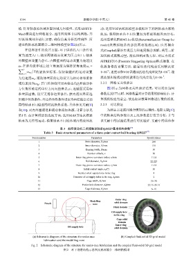
            建立的轴承流固耦合三维网格模型如图2(b)所示.                           model)来模拟轴承内部的两相湍流运动;应用耦合
                在边界条件的设置方面,环下供油孔入口条件设                          式(Coupled)算法实现压力和速度耦合求解,采用二阶
            置为速度入口,轴承两侧端面设置为压力出口;轴承                            迎风格式离散动量、湍流和相函数方程,对压力项采
            外圈壁面设置为静止,内圈壁面的运动设置为角速度                            用PRESTO! (Pressure Staggering Option)格式插值. 在

            ω,在腔内流体域上建立角速度为保持架角速度                     ω c =    收敛条件的设置方面,能量项迭代残差采用默认值
            ∑ Z     /
                                                                   −6
                                                                                                        −5
                  ω mj Z 的旋转坐标系,保持架壁面的运动设置                     1×10 ,速度项和VOF函数项的迭代残差设为1×10 ,湍
                j=1
                                                                                                     −4
            为角速度ω ,滚动体壁面的运动设置为相对相邻流体                           流动能和湍流动能耗散率迭代残差设为1×10 .
                      c
            域角速度为ω ,其自转轴线可用由姿态角β 和滚动体                           2.2.2    网格无关性验证
                                                  j
                        bj
            方位角所确定的单位方向向量来表示;近壁面采用标                                图3所示为网格无关性验证结果,可以看出当网
            准壁面函数,设置无滑移边界条件;腔内流固界面选                            格数达到377万时,网格数量对计算结果的影响较小,计
            用耦合传热条件,外边界传热条件设定为由经验公式估                           算规模较也为适宜,故选取该数量网格进行数值模拟.
            算的轴承不同壁面的对流换热系数,具体参见文献[8]                           2.2.3    对比验证
            和[18];对内外圈滚道和滚动体添加热源,计算方法见                             为验证上述流固耦合模型的正确性,选取文献[17]
            第1节. 在计算模型的选取方面,选用MRF方法来描述                         中的轴承结构参数以及工况参数进行仿真分析,并与
            轴承各元件的运动,模拟轴承不同流体域内的流体流                            该文献中的试验结果进行对比验证. 文献中的具体参

                                      表 3    航空发动机三点接触球轴承QJS227基本结构参数            [17]
                                                                                           [17]
                            Table 3    Basic structural parameters of a three point contact ball bearing QJS227
                     Serial number                       Parameters                         Specifications
                         1                           Outer diameter, D o /mm                   240
                         2                            Inner diameter, D i /mm                  135
                         3                            Bearing width, B/mm                      30
                         4                             Number of balls, z                      20
                         5                      Inner ring groove curvature radius, r i /mm   11.55
                         6                            Ball diameter, D b /mm                  22.225
                         7                      Outer ring groove curvature radius, r o /mm   11.55
                         8                           Initial contact angle, α 0 /(º)           30
                         9                       Number of oil supply holes in the ring         8
                        10                    Diameter of oil supply holes in the ring, d k /mm  2
                        11                             Cage width, B c /mm                    26~30
                        12                          Pocket hole diameter, d h /mm           22.16~26.16
                        13                           Cage thickness, H c /mm                  6~10


                                                                        Outer ring
                                                         Modelling
                            Nozzle                        zone          solid domain
                                                                       Fluid domain
                                                                      Oil supply hole
                                                                       in the ring
                                                                         Cage solid
                                                                          domain
                                                                        Inner ring
                                           Oil supply hole              solid domain


                     (a) Schematic diagram of the structure for under-race   (b) Coupled fluid-solid 3D grid model
                            lubrication and the modelling zone
                    Fig. 2    Schematic diagram of the structure for under-race lubrication and the coupled fluid-solid 3D grid model
                                        图 2    环下润滑结构示意图及流固耦合三维网格模型
   135   136   137   138   139   140   141   142   143   144   145