Page 107 - 摩擦学学报2025年第5期
P. 107

第 5 期                 王任侠, 等: 闸片摩擦块尺寸设计对高速列车制动振动噪声的调控作用                                      741


                                 Caliper
                                                                            3D model
                                                                           (Solid Works)
                                 Fixture
                        Disc                                            Finite element model
                                                                   ABAQUS  Static general analysis


                                     Block                        Node contact       Node sliding
                                                                stress distribution   distance
                                    (a)
                                                                 UMESHMOTION  +ALE  Wear depth and
                                                                           wear direction

                                                                           Grid and node
                                       F                                     updating

                                                                              Wear          No
                                    ω                                       simulation
                                                                              end?
                                                                            Yes
                                        F                                  End output
                                                                             results
                                    (b)                                       (c)

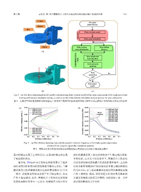
             Fig. 8    (a) The three-dimensional model and (b) corresponding finite element model of the main components of the high-speed train
                 braking performance simulation test rig, as well as (c) the finite element simulation analysis process for wear calculation
             图 8    高速列车制动性能模拟试验装置(a)主要部件三维模型和(b)相应的有限元模型以及(c)磨损计算的有限元仿真分析流程


                 (a)  0.10  Φ28.64 23rd                            (b)  18.30
                            Φ28.64 24th                                 18.25      coupling  Φ28.64 23rd
                                                                                             Φ28.64 24th
                            Φ31.84 23rd
                    Effective damping ration, ζ  0.00                  Unstable vibration frequency/kHz  18.20  Φ35.08 24th
                                                                                   Mode
                                                                                             Φ31.84 23rd
                            Φ31.84 24th
                                                                                             Φ31.84 24th
                      0.05
                                                                                             Φ35.08 23rd
                                                                                             Φ38.28 23rd
                                                                                             Φ38.28 24th
                                                                        18.15
                                                                        18.10
                     −0.05
                            Φ35.08 23rd
                            Φ35.08 24th
                            Φ38.28 23rd
                            Φ38.28 24th                                 18.05
                     −0.10                                              18.00
                        0.1  0.2  0.3  0.4  0.5  0.6  0.7                   0.1  0.2  0.3  0.4  0.5  0.6  0.7
                               Friction coefficient, μ                            Friction coefficient, μ
                     Fig. 9    (a) The effective damping ratio and (b) unstable vibration frequency of the brake system eigenvalues
                                         obtained from complex eigenvalue simulation analysis
                             图 9    复模态仿真分析得到的制动系统特征值(a)等效阻尼比和(b)不稳定振动频率
            第23阶模态出现了正的阻尼比,而第24阶模态则出现                          较低的摩擦系数下制动系统便会产生模态耦合现象.
            了相反的阻尼比.                                           尽管如此,在本文中研究条件下,摩擦块尺寸的变化
                相应地,图9(b)中显示系统在摩擦系数小于临界                        并没有改变制动系统耦合模态的阶数和频率,且复特
            值时其第23阶和第24阶模态频率不断相互靠近,当摩                          征值分析所预测的4个制动系统的不稳定振动频率均
            擦系数等于临界摩擦系数时这两阶模态耦合为1个单                            约为18 kHz,这与制动摩擦学试验获得的摩擦振动噪
            一频率. 该现象说明制动系统产生了模态耦合,从而                           声的主频相符. 因此,复特征值分析的结果是准确的
            产生不稳定振动. 此外,摩擦块尺寸的变化也使得制                           且建立的有限元模型是可靠的,该模型用于进一步开
            动系统复特征值存在一定差异,如摩擦尺寸较小时在                            展后续的瞬态动力学分析.
   102   103   104   105   106   107   108   109   110   111   112